MCP3905EV Microchip Technology, MCP3905EV Datasheet - Page 13
MCP3905EV
Manufacturer Part Number
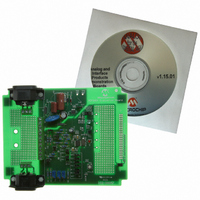
MCP3905EV
Description
BOARD DEMO FOR MCP3905
Manufacturer
Microchip Technology
Type
Other Power Managementr
Specifications of MCP3905EV
Main Purpose
Power Management, Energy/Power Meter
Embedded
No
Utilized Ic / Part
MCP3905/6
Primary Attributes
1-Phase, 120/220 VAC, On Board Transformerless AC/DC 5V Supply
Silicon Manufacturer
Microchip
Silicon Core Number
MCP3905A
Kit Application Type
Power Management
Application Sub Type
Energy Meter
Kit Contents
Board & Design Guides
Product
Power Management Modules
Lead Free Status / RoHS Status
Contains lead / RoHS non-compliant
Secondary Attributes
-
Lead Free Status / Rohs Status
Lead free / RoHS Compliant
For Use With/related Products
MCP3905
Lead Free Status / RoHS Status
Lead free / RoHS Compliant, Contains lead / RoHS non-compliant


© 2005 Microchip Technology Inc.
2.3.2
Resistor sockets R
JP14 should also be open. This configuration puts the shunt across the channel inputs
differentially with the users option of a RC filter.
FIGURE 2-3:
2.3.3
Using JP18, JP19, JP20 and JP21, select if Channel 1 will be single-ended or
differential, and which input will be tied to the voltage divider and potentiometer. In
Figure 2-4, the voltage divider and potentiometer are connected to the positive input,
while the negative input is connected to A
FIGURE 2-4:
Step 2: Select Channel 0 Input Method
Step 3: Select Channel 1 Input Method
+
-
11
Channel 0 Jumpers for 250 µ
Channel 1 Input Method Example.
and R
Potentiometer (Circuit A)
RC to Voltage Divider &
12
should be left open when using a shunt. JP3, JP13 and
1 kΩ
R
1
Installation and Operation
open
JP3
GND
C
0.033 µF
1
JP13
JP14
through the RC.
Ω
Shunt Selection.
1 kΩ
1 kΩ
R
R
1
1
JP20
JP21
JP18
JP19
C
0.033 µF
C
0.033 µF
1
1
DS51567A-page 9
CH1+
CH1+
CH1-
CH1-
CH0+
CH0-
Related parts for MCP3905EV
Image
Part Number
Description
Manufacturer
Datasheet
Request
R

Part Number:
Description:
Manufacturer:
Microchip Technology Inc.
Datasheet:
Part Number:
Description:
Manufacturer:
Microchip Technology Inc.
Datasheet:
Part Number:
Description:
Manufacturer:
Microchip Technology Inc.
Datasheet:
Part Number:
Description:
Manufacturer:
Microchip Technology Inc.
Datasheet:
Part Number:
Description:
Manufacturer:
Microchip Technology Inc.
Datasheet:
Part Number:
Description:
Manufacturer:
Microchip Technology Inc.
Datasheet:
Part Number:
Description:
Manufacturer:
Microchip Technology Inc.
Datasheet:
Part Number:
Description:
Manufacturer:
Microchip Technology Inc.
Datasheet: