MCP3905EV Microchip Technology, MCP3905EV Datasheet - Page 15
MCP3905EV
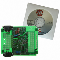
Manufacturer Part Number
MCP3905EV
Description
BOARD DEMO FOR MCP3905
Manufacturer
Microchip Technology
Type
Other Power Managementr
Specifications of MCP3905EV
Main Purpose
Power Management, Energy/Power Meter
Embedded
No
Utilized Ic / Part
MCP3905/6
Primary Attributes
1-Phase, 120/220 VAC, On Board Transformerless AC/DC 5V Supply
Silicon Manufacturer
Microchip
Silicon Core Number
MCP3905A
Kit Application Type
Power Management
Application Sub Type
Energy Meter
Kit Contents
Board & Design Guides
Product
Power Management Modules
Lead Free Status / RoHS Status
Contains lead / RoHS non-compliant
Secondary Attributes
-
Lead Free Status / Rohs Status
Lead free / RoHS Compliant
For Use With/related Products
MCP3905
Lead Free Status / RoHS Status
Lead free / RoHS Compliant, Contains lead / RoHS non-compliant


2.4
2.5
© 2005 Microchip Technology Inc.
MCP3905/6 EVALUATION BOARD OVERVIEW
FUNCTIONAL BLOCK DESCRIPTIONS
The functional blocks of the MCP3905/06 Evaluation Board will be described in this
section. For more detailed information regarding design decisions and approaches to
IEC1036 compliance, refer to AN994, “IEC Compliant Active Energy Meter Design
Using The MCP3905/6” (DS00994). For a detailed circuit schematic, refer to Appendix
A. “Schematics and Layouts” and Appendix B. “Bill-Of-Materials (BOM)” for a list
of the parts used to build the MCP3905/6 Evaluation Board.
2.5.1
All line/load, shunt and CT connections are to be made next to the screw-type
connectors J5-J12. This area includes two mounting holes for a standard shunt
connector. All high-voltage connections go onto this prototype area.
2.5.2
These screw-type connections are for shunts, CTs, line and load. The shunt resistance
should be placed in parallel with J5 and J6. A variety of experiments using shunts and
CTs can be performed here in conjunction with the input prototype area.
J9 and J10 feed the AC/DC power supply circuitry. J10 is the reference connection to
the entire board. Shunt-type meters should be connected to the line-side. One example
is given in the figure below.
FIGURE 2-6:
2.5.3
Jumpers and shunts for both logic-high and logic-low are included for all gain and
frequency constant selections, with filter options Off and On columns being clearly
labelled.
FIGURE 2-7:
\
J11
Input Prototype Area
High-Voltage Input Connections (J5-12)
Jumpers and Shunts for MCP3905 Gain and Frequency
Constant F
Example Wiring Using Two-Wire System with Shunt
MCP3905 Jumper Selections
C
Selection (JP1, 2, 9-12)
High Low
Installation and Operation
250 µΩ Shunt
CH0+ CH0- CH1A CH1B
DS51567A-page 11
J12
Related parts for MCP3905EV
Image
Part Number
Description
Manufacturer
Datasheet
Request
R

Part Number:
Description:
Manufacturer:
Microchip Technology Inc.
Datasheet:
Part Number:
Description:
Manufacturer:
Microchip Technology Inc.
Datasheet:
Part Number:
Description:
Manufacturer:
Microchip Technology Inc.
Datasheet:
Part Number:
Description:
Manufacturer:
Microchip Technology Inc.
Datasheet:
Part Number:
Description:
Manufacturer:
Microchip Technology Inc.
Datasheet:
Part Number:
Description:
Manufacturer:
Microchip Technology Inc.
Datasheet:
Part Number:
Description:
Manufacturer:
Microchip Technology Inc.
Datasheet:
Part Number:
Description:
Manufacturer:
Microchip Technology Inc.
Datasheet: