MCP3905EV Microchip Technology, MCP3905EV Datasheet - Page 20
MCP3905EV
Manufacturer Part Number
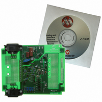
MCP3905EV
Description
BOARD DEMO FOR MCP3905
Manufacturer
Microchip Technology
Type
Other Power Managementr
Specifications of MCP3905EV
Main Purpose
Power Management, Energy/Power Meter
Embedded
No
Utilized Ic / Part
MCP3905/6
Primary Attributes
1-Phase, 120/220 VAC, On Board Transformerless AC/DC 5V Supply
Silicon Manufacturer
Microchip
Silicon Core Number
MCP3905A
Kit Application Type
Power Management
Application Sub Type
Energy Meter
Kit Contents
Board & Design Guides
Product
Power Management Modules
Lead Free Status / RoHS Status
Contains lead / RoHS non-compliant
Secondary Attributes
-
Lead Free Status / Rohs Status
Lead free / RoHS Compliant
For Use With/related Products
MCP3905
Lead Free Status / RoHS Status
Lead free / RoHS Compliant, Contains lead / RoHS non-compliant


MCP3905/06
The
integration times and, thus, higher frequencies. The
output frequency value can be calculated with the
following equation:
EQUATION 4-2:
The constant HF
digital settings with the
The detailed timings of the output pulses are described
in the Timing Characteristics table (see Section 1.0
“Electrical Characteristics” and
TABLE 4-4:
DS21948E-page 20
Where:
V
F2
REF
0
0
0
0
1
1
1
1
F
V
V
G = the PGA gain on Channel 0
C
0
1
high-frequency
HF
= the RMS differential voltage on Channel 0
= the RMS differential voltage on Channel 1
= the frequency constant selected
= the voltage reference
OUT
(current channel)
F1
0
0
1
1
0
0
1
1
(
Hz
C
)
F0
OUTPUT FREQUENCY CONSTANT HF
0
1
0
1
0
1
0
1
depends on the F
=
HF
OUTPUT EQUATION
8.06
--------------------------------------------------------------- -
Table
output
OUT
2048 x F
×
128 x F
64 x F
32 x F
16 x F
64 x F
32 x F
16 x F
V
4-4.
HF
0
(
FREQUENCY
V
×
C
HF
REF
V
Figure
C
C
C
C
C
C
1
C
C
OUT
×
)
2
OUT0
G
×
1-1).
HF
has
and F
C
MCLK/2
MCLK/2
MCLK/2
MCLK/2
MCLK/2
MCLK/2
MCLK/2
HF
MCLK/2
lower
OUT1
C
(Hz)
15
15
15
16
16
16
16
7
MINIMAL OUTPUT FREQUENCY FOR
NO-LOAD THRESHOLD
The MCP3905/06 also includes, on each output
frequency, a no-load threshold circuit that will eliminate
any creep effects in the meter. The outputs will not
show any pulse if the output frequency falls below the
no-load threshold. The minimum output frequency on
F
maximum output frequency (respectively F
for each of the F2, F1 and F0 selections (see
and
last configuration, the no-load threshold feature is
disabled. The selection of F
current load. In order to respect the IEC standards
requirements, the meter will have to be designed to
allow start-up currents compatible with the standards
by
requirements. For additional applications information
on no-load threshold, startup current and other meter
design points, refer to AN994, "IEC Compliant Active
Energy Meter Design Using The MCP3905/6”,
(DS00994).
C
(MCLK = 3.58 MHz)
OUT0/1
FOR HF
Table
choosing
27968.75
HF
109.25
109.25
109.25
219.51
219.51
219.51
219.51
and HF
C
4-4); except when F2, F1, F0 = 011. In this
(Hz)
OUT
the
(V
OUT
REF
FC
is equal to 0.0015% of the
© 2009 Microchip Technology Inc.
HF
= 2.4V)
C
OUT
full-scale AC Inputs
value
will determine the start-up
Frequency (Hz) with
6070.12
27.21
27.21
27.21
47.42
47.42
47.42
47.42
matching
C
and HF
Table 4-3
these
C
)
Related parts for MCP3905EV
Image
Part Number
Description
Manufacturer
Datasheet
Request
R

Part Number:
Description:
Manufacturer:
Microchip Technology Inc.
Datasheet:
Part Number:
Description:
Manufacturer:
Microchip Technology Inc.
Datasheet:
Part Number:
Description:
Manufacturer:
Microchip Technology Inc.
Datasheet:
Part Number:
Description:
Manufacturer:
Microchip Technology Inc.
Datasheet:
Part Number:
Description:
Manufacturer:
Microchip Technology Inc.
Datasheet:
Part Number:
Description:
Manufacturer:
Microchip Technology Inc.
Datasheet:
Part Number:
Description:
Manufacturer:
Microchip Technology Inc.
Datasheet:
Part Number:
Description:
Manufacturer:
Microchip Technology Inc.
Datasheet: