ATDVK90CAN1 Atmel, ATDVK90CAN1 Datasheet - Page 31
ATDVK90CAN1
Manufacturer Part Number
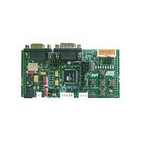
ATDVK90CAN1
Description
KIT DEV FOR AT90CAN128 MCU
Manufacturer
Atmel
Specifications of ATDVK90CAN1
Main Purpose
*
Embedded
*
Utilized Ic / Part
AT90CAN AVR Devices
Primary Attributes
*
Secondary Attributes
*
Processor To Be Evaluated
AT90CAN
Data Bus Width
8 bit
Interface Type
RS-232, SPI, TWI
Core Architecture
AVR
Core Sub-architecture
AVR UC3
Kit Contents
Board, AT90CAN128 Sample Microcontroller, 9V Battery Power Cable, CD-ROM, Manuals
Features
RS232, CAN, LIN, SPI & TWI Serial Interface
Rohs Compliant
Yes
Lead Free Status / RoHS Status
Contains lead / RoHS non-compliant
Available stocks
Company
Part Number
Manufacturer
Quantity
Price
Company:

Part Number:
ATDVK90CAN1
Manufacturer:
Atmel
Quantity:
135


4381B–AVR–07/08
Using the DVK90CAN1
3.7.7
3-30
Temperature Sensor
The voltage input can be configured. It can be either the board supply voltage (VCC) or
an external input on T11 test pin. To improve the connection, close to T11, there is the
test pin T12 wrapped to GND.
Table 3-14 . Voltage Input Switch Configuration
The temperature sensor uses a thermistor, or temperature-sensitive resistor. This
thermistor have a negative temperature coefficient (NTC), meaning the resistance goes
up as temperature goes down. Of all passive temperature measurement sensors,
thermistors have the highest sensitivity (resistance change per degree of temperature
change). Thermistors do not have a linear temperature/resistance curve.
The voltage over the NTC can be found using the A/D converter. See the AT90CAN128
Datasheet for how to use the ADC. The thermistor value (R
following expression:
The NTC thermistor used in DVK90CAN1 has a resistance of 100 KΩ
and a beta-value of 4250 ±3%. By the use of the following equation, the temperature (T)
can be calculated:
The following cross table also can be used. It is based on the above equation.
Mode
VCC
R
T
Where:
Where:
=
(
R
H
⋅
V
T
ADC0
=
R
R
V
VCC = Board power supply
R
ß
R
T
-------------------------------
⎛
⎝
0
ADC0
T
H
T
0
ln
= 4250 ±3%
)
= 298 °K (273 °K + 25°K)
= 100 KΩ
= Thermistor value (Ω) at T temperature (°Kelvin)
= Thermistor value (Ω) at T temperature (°Kelvin)
= Second resistor of the bridge -100 KΩ
⁄
R
------ -
R
(
View
T
V
0
β
= Voltage value on ADC-0 input (V)
⎞
⎠
CC
+
----- -
T
β
–
0
±
V
5% at 25°C
ADC0
)
External
Input
Mode
(T11)
±
DVK90CAN1 Hardware User Guide
10% at 25°C
T
) is calculate with the
View
±
5% at 25°C (T
T11 = VIN
T12 = GND
0
)
Related parts for ATDVK90CAN1
Image
Part Number
Description
Manufacturer
Datasheet
Request
R

Part Number:
Description:
DEV KIT FOR AVR/AVR32
Manufacturer:
Atmel
Datasheet:

Part Number:
Description:
INTERVAL AND WIPE/WASH WIPER CONTROL IC WITH DELAY
Manufacturer:
ATMEL Corporation
Datasheet:
Part Number:
Description:
Low-Voltage Voice-Switched IC for Hands-Free Operation
Manufacturer:
ATMEL Corporation
Datasheet:
Part Number:
Description:
MONOLITHIC INTEGRATED FEATUREPHONE CIRCUIT
Manufacturer:
ATMEL Corporation
Datasheet:
Part Number:
Description:
AM-FM Receiver IC U4255BM-M
Manufacturer:
ATMEL Corporation
Datasheet:
Part Number:
Description:
Monolithic Integrated Feature Phone Circuit
Manufacturer:
ATMEL Corporation
Datasheet:
Part Number:
Description:
Multistandard Video-IF and Quasi Parallel Sound Processing
Manufacturer:
ATMEL Corporation
Datasheet:
Part Number:
Description:
High-performance EE PLD
Manufacturer:
ATMEL Corporation
Datasheet:
Part Number:
Description:
8-bit Flash Microcontroller
Manufacturer:
ATMEL Corporation
Datasheet:
Part Number:
Description:
2-Wire Serial EEPROM
Manufacturer:
ATMEL Corporation
Datasheet: