DV251001 Microchip Technology, DV251001 Datasheet - Page 17
DV251001
Manufacturer Part Number
DV251001
Description
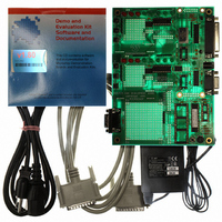
KIT DEVELOPMENT CAN MCP2510
Manufacturer
Microchip Technology
Specifications of DV251001
Main Purpose
Interface, CAN Controller
Embedded
Yes, MCU, 8-Bit
Utilized Ic / Part
MCP2510, MCP2515
Primary Attributes
Stand alone CAN Controller with SPI
Silicon Manufacturer
Microchip
Application Sub Type
CAN
Kit Application Type
Interface
Silicon Core Number
MCP2510, MCP2515
Kit Contents
Board Cable Power Supply CD
Lead Free Status / RoHS Status
Lead free / RoHS Compliant
Secondary Attributes
-
Lead Free Status / RoHS Status
na, Lead free / RoHS Compliant
Other names
DV251001R
DV251001R
DV251001R
Available stocks
Company
Part Number
Manufacturer
Quantity
Price
Company:

Part Number:
DV251001
Manufacturer:
MICROCHIP
Quantity:
12 000


3.6
2003 Microchip Technology Inc.
HARDWARE OVERVIEW
The target board consists of two CAN nodes (MCU, MCP2515), a transceiver, an
embedded CAN bus and support components.
The two nodes are connected to the embedded bus. By default, the embedded CAN
bus is connected to the CAN connector (DB9), which is a link to an external CAN bus.
The support components are defined as all of the components that interface with the
nodes as controls, indicators and other peripherals.
Figure 3-5 shows the main components of the board.
LPT Port
COM Port
Oscillators
PICmicro MCU
Sockets
MCU Prototype
Area
Nonvolatile
Memory
MCP2515
CAN Transceiver
LED Banks
RTS Buttons
CAN Connector
The link between the MCP2515 and the PC that acts as the
MCU for node0. The parallel port is used to allow the PC to
communicate with MCP2515 via SPI.
The communications port (COM) is connected to the PICmicro
MCU sockets (USART pins) via a MAX-232 device so that serial
communication is possible between the PICmicro MCU and PC.
The three oscillator socket’s outputs are connected together by
default, so only one oscillator is needed to clock both MCP2515s
and the PICmicro MCU. By cutting traces and installing jumpers,
other oscillator configurations can be achieved. See Chapter 5
“Reconfigure the Hardware” for more detail on configuring the
oscillator sockets.
Three sockets are provided to give the user a wide range of
PICmicro MCUs to choose from when developing firmware.
This area was created for prototyping MCUs that are not
supported with the sockets or for prototyping complete CAN
nodes.
Use of the 64-kbit SPI EEPROM is defined by the user. Since it
is on the same SPI bus as the MCP2515, care has to be taken to
utilize the chip selects properly.
The MCP2515 is the interface between the CAN bus and the
MCU.
The CAN transceiver converts the differential signal on the bus
to digital levels for the CAN controller and vice versa.
The LED banks reflect the state of many of the pins on the
MCP2515.
These buttons are used to request transmission of the
corresponding MCP2515’s transmit buffer if the pin is configured
as RTS inputs or used as digital inputs.
The CAN connector is used to connect the
MCP2515 Development Kit to an external bus.
DS51416A-page 13
Related parts for DV251001
Image
Part Number
Description
Manufacturer
Datasheet
Request
R

Part Number:
Description:
Manufacturer:
Microchip Technology Inc.
Datasheet:
Part Number:
Description:
Manufacturer:
Microchip Technology Inc.
Datasheet:
Part Number:
Description:
Manufacturer:
Microchip Technology Inc.
Datasheet:
Part Number:
Description:
Manufacturer:
Microchip Technology Inc.
Datasheet:
Part Number:
Description:
Manufacturer:
Microchip Technology Inc.
Datasheet:
Part Number:
Description:
Manufacturer:
Microchip Technology Inc.
Datasheet:
Part Number:
Description:
Manufacturer:
Microchip Technology Inc.
Datasheet:
Part Number:
Description:
Manufacturer:
Microchip Technology Inc.
Datasheet: