DV251001 Microchip Technology, DV251001 Datasheet - Page 34
DV251001
Manufacturer Part Number
DV251001
Description
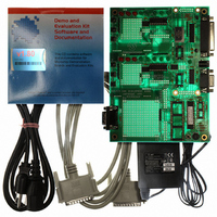
KIT DEVELOPMENT CAN MCP2510
Manufacturer
Microchip Technology
Specifications of DV251001
Main Purpose
Interface, CAN Controller
Embedded
Yes, MCU, 8-Bit
Utilized Ic / Part
MCP2510, MCP2515
Primary Attributes
Stand alone CAN Controller with SPI
Silicon Manufacturer
Microchip
Application Sub Type
CAN
Kit Application Type
Interface
Silicon Core Number
MCP2510, MCP2515
Kit Contents
Board Cable Power Supply CD
Lead Free Status / RoHS Status
Lead free / RoHS Compliant
Secondary Attributes
-
Lead Free Status / RoHS Status
na, Lead free / RoHS Compliant
Other names
DV251001R
DV251001R
DV251001R
Available stocks
Company
Part Number
Manufacturer
Quantity
Price
Company:

Part Number:
DV251001
Manufacturer:
MICROCHIP
Quantity:
12 000


5.4
DS51416A-page 30
OSCILLATOR CONFIGURATIONS
5.3.2
This configuration is the same as above, with the exception that it is connected to an
external CAN bus via the CAN connector (DB9).
Typically, this configuration would be used to further evaluate the MCP2515 by
observing how it functions on an external CAN bus. Experimentation with bit timings,
masks and filters, interrupts, RTS pins, etc. can be performed while using the Register
template. While in the configuration, simple bus monitoring can be achieved using the
Basic template.
5.3.3
This configuration utilizes node 0 and node 1 to create a two node, embedded system
(no external bus).
This configuration can be used for evaluation or development. The microcontroller
firmware is being developed at this point. As an example, the firmware may be written
to observe how the MCP2515 uses masks and filters to accept/reject messages. SPI
modules and interrupt handlers may be under development at this stage.
5.3.4
This configuration places both nodes on the CAN bus.
One scenario utilizes the microcontroller node as the node under development, while
the PC node is simply a bus monitor to assist in debugging.
5.3.5
This configuration places the microcontroller node (node 1) on the CAN bus.
There are three oscillator sockets. By default, both MCP2515s and the PICmicro
MCU sockets use a common oscillator. Since all three socket outputs are tied together,
the oscillator can be placed in any socket.
It is possible for each node and the microcontrollers to have their own oscillator by
configuring the jumpers as described later in this chapter.
Warning: Care must be taken when installing more than one oscillator. The jumper
PC Node Distributed (one node, on CAN bus)
Two Node Embedded System
Two Node Distributed System
Microcontroller Distributed System (One Node)
settings must be correct or contention will occur at some or all of the
device oscillator inputs. This could have catastrophic results.
2003 Microchip Technology Inc.
®
Related parts for DV251001
Image
Part Number
Description
Manufacturer
Datasheet
Request
R

Part Number:
Description:
Manufacturer:
Microchip Technology Inc.
Datasheet:
Part Number:
Description:
Manufacturer:
Microchip Technology Inc.
Datasheet:
Part Number:
Description:
Manufacturer:
Microchip Technology Inc.
Datasheet:
Part Number:
Description:
Manufacturer:
Microchip Technology Inc.
Datasheet:
Part Number:
Description:
Manufacturer:
Microchip Technology Inc.
Datasheet:
Part Number:
Description:
Manufacturer:
Microchip Technology Inc.
Datasheet:
Part Number:
Description:
Manufacturer:
Microchip Technology Inc.
Datasheet:
Part Number:
Description:
Manufacturer:
Microchip Technology Inc.
Datasheet: