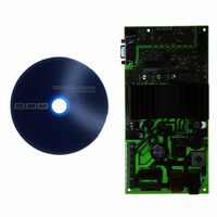
ATAVRMC200 Atmel, ATAVRMC200 Datasheet - Page 9

ATAVRMC200
Manufacturer Part Number
ATAVRMC200
Description
KIT EVAL FOR AT90PWM3 ASYNC
Manufacturer
Atmel
Series
AVR®r
Specifications of ATAVRMC200
Main Purpose
Power Management, Motor Control
Embedded
Yes, MCU, 8-Bit
Utilized Ic / Part
AT90PWM3
Primary Attributes
AC Asynchronous Motors & Brushless DC (BLDC) Motors
Secondary Attributes
Short-Circuit & Thermal Protection
Processor To Be Evaluated
AT90PWM3
Interface Type
RS-232, ISP
Applications
Motor Control
Lead Free Status / RoHS Status
Lead free / RoHS Compliant
3.2
3.2.1
ATAVRMC200 Hardware User Guide
Power Supply
Power Supply
The power supply source must be 110V AC to 230V AC (50/60 Hz) on J1 connector.
Three differents voltages are generated from AC source to power the board.
•
•
•
LED1 is always lit when VBridge power is applied to ATAVRMC200.
During microcode debugging phase, the user must power the board directly with
VDC= 48V DC through J1 connector (PH and N connection), it will allow to check the
signal on oscilloscope and use DebugWire interface (J3) to program and debug micro-
code for AT90PWM3 part.
Warning: When using DebugWire or ISP interface through J3 connector for debugging
or programming, board must not be powered with 110-220V AC source but only with
48V DC.
Figure 3-2 . Power supply Connector
VDC = 325V DC (with 220V AC as input source) for motor phases
VBridge = 15V DC for drivers control.
and VDD = 5V DC for cpu power supply.
LED 1
7638A–AVR–05/06
6


