DEMOBOARD-U4091BM Atmel, DEMOBOARD-U4091BM Datasheet - Page 18
DEMOBOARD-U4091BM
Manufacturer Part Number
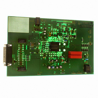
DEMOBOARD-U4091BM
Description
BOARD DEMO FOR U4091BM
Manufacturer
Atmel
Datasheet
1.DEMOBOARD-U4091BM.pdf
(38 pages)
Specifications of DEMOBOARD-U4091BM
Main Purpose
Telecom, Phone IC, Corded
Embedded
No
Utilized Ic / Part
U4091BM
Primary Attributes
DTMF, Speech Circuit, Tone-ringer, Voice Switch
Secondary Attributes
Serial Bus MCU Interface
Interface Type
Serial
Operating Voltage
12 V
Operating Temperature Range
- 22 C to + 75 C
Lead Free Status / RoHS Status
Contains lead / RoHS non-compliant
For Use With/related Products
U4091BM


12.1
12.2
12.3
18
Dial-tone Detector
Background Noise Monitors
4-point Sensing
U4091BM-R
The dial-tone detector is a comparator with one side connected to the speaker amplifier input
and the other to VM with a 35-mV offset (see
mode, and the incoming signal is greater than 35 mV (25 mV
change thus disabling the receive idle mode. This circuit prevents the dial tone (which would be
considered as continuous noise) from fading away as the circuit would have the tendency to
switch to idle mode. By disabling the receive idle mode, the dial tone remains at the normally
expected full level.
This circuit distinguishes speech (which consists of bursts) from background noise (a relatively
constant signal level). There are two background-noise monitors, one for the receive path and
the other for the transmit path. The receive background-noise monitor is operated on by the
receive level detector, while the transmit background noise monitor is operated on by the trans-
mit level detector (see
DC voltage representative of the respective noise levels in capacitors at CBNMR and CBNMT.
The voltages at these pins have slow rise times (determined by the internal current source and
an external capacitor), but fast decay times. If the signal at TLDR (or TLDT) changes slowly, the
voltage at BNMR (or BNMT) will remain more positive than the voltage at the non-inverting input
of the monitor's output comparator. When speech is present, the voltage at the non-inverting
input of the comparator will rise more quickly than the voltage at the inverting input (due to the
burst characteristic of speech), causing its output to change. This output is sensed by the mode-
control block.
In 4-point-sensing mode, the receive- and the transmit-sensing paths include additional CLOGs
(calculated logarithmic amplifiers). The block MODECON compares the detector output signals
and decides whether receive, transmit or idle mode has to be activated. Depending on the mode
decision, MODECON generates a differential voltage to control AFSCON.
The MODECON block has seven inputs:
The differential output (AFST, AFSR) of the block MODECON controls AFSCON. The effect of
I1-I4 in
• The output of the transmit log (LOGT) – the comparison of LOGT, CLOGR
• The output of the receive clog (CLOGR) – designated I1
• The output of the transmit clog (CLOGT) – the comparison of CLOGT, LOGR
• The output of the receive log (LOGR) – designated I2
• The output of the transmit background-noise monitor (BNMT) – designated I3
• The output of the receive background-noise monitor (BNMR) – designated I4
• The output of the dial-tone detector
Table 12-1 on page
Figure 12-6 on page
19.
21). They monitor the background noise by storing a
Figure 12-5 on page
rms
), the comparator's output will
21). If the circuit is in idle
4872A–CORD–08/05
Related parts for DEMOBOARD-U4091BM
Image
Part Number
Description
Manufacturer
Datasheet
Request
R

Part Number:
Description:
BOARD DEMO FOR T7024PGM
Manufacturer:
Atmel
Datasheet:


Part Number:
Description:
BOARD DEMO FOR U3600BM
Manufacturer:
Atmel
Datasheet:

Part Number:
Description:
BOARD DEMO FOR ATR2806
Manufacturer:
Atmel
Datasheet:
Part Number:
Description:
BOARD DEMO COM-I/Q MOD 1GHZ
Manufacturer:
Atmel
Datasheet:

Part Number:
Description:
Banana & Binding Post Connectors SINGLE PCB SOCK BLK
Manufacturer:
DEM Manufacturing
Datasheet:
Part Number:
Description:
Banana & Binding Post Connectors PLUG RED
Manufacturer:
DEM Manufacturing
Datasheet:
Part Number:
Description:
Banana & Binding Post Connectors SINGLE PCB SOCK RED
Manufacturer:
DEM Manufacturing
Datasheet:
Part Number:
Description:
DIN Connectors SOCKET NICKEL 8 PIN
Manufacturer:
DEM Manufacturing
Datasheet:
Part Number:
Description:
DIN Connectors PLUG NICKEL 3 PIN
Manufacturer:
DEM Manufacturing
Datasheet: