DEMOBOARD-U4091BM Atmel, DEMOBOARD-U4091BM Datasheet - Page 6
DEMOBOARD-U4091BM
Manufacturer Part Number
DEMOBOARD-U4091BM
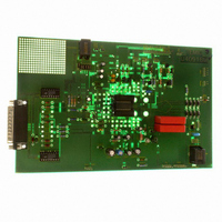
Description
BOARD DEMO FOR U4091BM
Manufacturer
Atmel
Datasheet
1.DEMOBOARD-U4091BM.pdf
(38 pages)
Specifications of DEMOBOARD-U4091BM
Main Purpose
Telecom, Phone IC, Corded
Embedded
No
Utilized Ic / Part
U4091BM
Primary Attributes
DTMF, Speech Circuit, Tone-ringer, Voice Switch
Secondary Attributes
Serial Bus MCU Interface
Interface Type
Serial
Operating Voltage
12 V
Operating Temperature Range
- 22 C to + 75 C
Lead Free Status / RoHS Status
Contains lead / RoHS non-compliant
For Use With/related Products
U4091BM


Table 2-1.
3. DC Line Interface and Supply-voltage Generation
4. Supply Structure of the Chip
6
Note:
Pin
40
41
42
43
44
1. The protection device at pin RECIN is disconnected.
U4091BM-R
Pin Description
AMREC
Symbol
AMPB
STRC
STO
STC
The DC line interface consists of an electronic inductance and a dual-port output stage which
charges the capacitors at VMPS and VB. The value of the equivalent inductance is given by:
The U4091BM-R contains two identical series regulators which provide a supply voltage VMP of
3.3V suitable for a microprocessor. In speech mode, both regulators are active because VMPS
and VB are charged simultaneously by the DC line interface. The output current is 6 mA. The
capacitor at VMPS is used to provide the microcomputer with sufficient power during long line
interruptions. Thus, long flash pulses can be bridged or an LCD display can be turned on for
more than 2 seconds after going on-hook. When the system is in ringing mode, VB is charged by
the on-chip ringing power converter. In this mode, only one regulator is used to supply VMP with
maximum 3 mA.
A main benefit of the U4091BM is the easy implementation of various applications due to the
flexible system structure of the chip.
Possible applications:
The special supply topology for the various functional blocks is shown in
There are four major supply states:
L
Function
Input for playback signal of answering machine
Output for recording signal of answering machine
Output for connecting the sidetone network
Input for sidetone network
Input for sidetone network
• Group listening phone
• Hands-free phone
• Phones which feature ringing with the built-in speaker amplifier
• Answering machine with external supply
1. Speech condition
=
2
------------------------------------------------------------------------------------------ -
In speech condition, the system is supplied by the line current. If the LIDET block
detects a line voltage above approximately 2V, the internal signal VLON is activated.
This is detected via the serial bus, all the blocks which are needed have to be switched
on via the serial bus.
For line voltages below 2V, the switches remain in quiescent state as shown in the
diagram.
R
SENSE
R
DC
C
IND
+
R
30
R
DC
R
30
Figure 4-1 on page
4872A–CORD–08/05
7.
Related parts for DEMOBOARD-U4091BM
Image
Part Number
Description
Manufacturer
Datasheet
Request
R

Part Number:
Description:
BOARD DEMO FOR T7024PGM
Manufacturer:
Atmel
Datasheet:


Part Number:
Description:
BOARD DEMO FOR U3600BM
Manufacturer:
Atmel
Datasheet:

Part Number:
Description:
BOARD DEMO FOR ATR2806
Manufacturer:
Atmel
Datasheet:
Part Number:
Description:
BOARD DEMO COM-I/Q MOD 1GHZ
Manufacturer:
Atmel
Datasheet:

Part Number:
Description:
Banana & Binding Post Connectors SINGLE PCB SOCK BLK
Manufacturer:
DEM Manufacturing
Datasheet:
Part Number:
Description:
Banana & Binding Post Connectors PLUG RED
Manufacturer:
DEM Manufacturing
Datasheet:
Part Number:
Description:
Banana & Binding Post Connectors SINGLE PCB SOCK RED
Manufacturer:
DEM Manufacturing
Datasheet:
Part Number:
Description:
DIN Connectors SOCKET NICKEL 8 PIN
Manufacturer:
DEM Manufacturing
Datasheet:
Part Number:
Description:
DIN Connectors PLUG NICKEL 3 PIN
Manufacturer:
DEM Manufacturing
Datasheet: