HFBR-0501 Avago Technologies US Inc., HFBR-0501 Datasheet - Page 18
HFBR-0501
Manufacturer Part Number
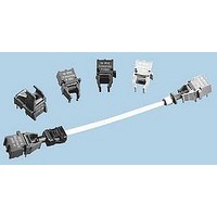
HFBR-0501
Description
KIT EVAL FIBER OPTIC 5MBD
Manufacturer
Avago Technologies US Inc.
Datasheet
1.HFBR-2521.pdf
(19 pages)
Specifications of HFBR-0501
Main Purpose
Interface, Fiber Optics
Embedded
No
Utilized Ic / Part
HFBR-0501 series
Primary Attributes
1MBd @ 70m, 40 kBd @120m
Secondary Attributes
6 mA Peak
Silicon Core Number
HFBR-1524, HFBR-2524
Kit Contents
TX/RX Mods, Cable, Pol Kit, SW, Pwr. Sup
Silicon Family Name
Versatile Link
Features
Dc To 5 MBd TTL Compatible Fiber Optic Component
Lead Free Status / RoHS Status
Lead free / RoHS Compliant
Lead Free Status / RoHS Status
Lead free / RoHS Compliant, Lead free / RoHS Compliant
Other names
516-2141
HFBR-0501
HFBR-0501


HFBR-25X3 Receiver
Receiver Electrical/Optical Characteristics
Notes:
1. Measured at the end of the fiber optic cable with large area detector.
2. Optical flux, P (dBm) = 10 Log P( W)/1000 W.
3. Because of the very high sensitivity of the HFBR-25X3, the digital output may switch in response to ambient light levels when a cable is not
4. Including current in 3.3 k pull-up resistor.
18
Absolute Maximum Ratings
Notes:
1. 1.6 mm below seating plane.
2. It is essential that a bypass capacitor 0.01 F be connected from pin 2 to pin 3 of the receiver.
Parameter
Input Optical Power
Level Logic 0
Input Optical Power
Level Logic 1
High Level Output Voltage
Low Level Output Voltage
High Level Supply Current
Low Level Supply Current
Effective Diameter
Numerical Aperture
occupying the receiver optical port. The designer should take care to filter out signals from this source if they pose a hazard to the system.
Parameter
Storage Temperature
Operating Temperature
Lead Soldering Cycle
Supply Voltage
Average Output Collector Current
Output Collector Power Dissipation
Output Voltage
DO NOT CONNECT
DO NOT CONNECT
5
8
Time
Temp.
Symbol
P
P
I
V
I
NA
V
CCH
CCL
R(H)
R(L)
D
OH
OL
4
3
2
1
V
OPEN
GROUND
V
CC
O
0 C to 70 C, 4.5 V V
Min.
–39
–39
2.4
Symbol
P
V
T
V
T
I
CC
OD
O
A
O
S
Typ.
1.2
2.9
0.5
1
–13.7
–13.3
Max.
–53
CC
1.9
3.7
0.4
Min.
–0.5
–0.5
–40
–40
5.5 V unless otherwise specified.
–1
Units
dBm
dBm
mm
mA
mA
V
V
Note: Pins 5 and 8 are for mounting and retaining
purposes only. Do not electrically connect these pins.
Pin #
1
2
3
4
5
8
Max.
+85
+85
260
Conditions
V
V
I
V
I
I
I
P
V
V
P
10
25
OL
OH
OH
O
7
5
7
O
O
OH
CC
CC
R
R
= -40 A, P
= V
= V
= 3.2 mA
= P
= P
= 40 A
= 8 mA, 25 C
= 5.5 V, P
= 5.5 V,
= 5.5 V
OL
OL
R(L)MIN
RL
, I
,
(MIN)
OL
Function
V
Ground
Open
V
Do not connect
Do not connect
= 3.2 mA
Units
O
CC
mW
R
sec
mA
R
V
V
= 0 W
C
C
C
= 0 W
Reference
Note 1
Note 2
Ref.
Notes 1,
Note 3
Note 4
Note 4
2, 3
Related parts for HFBR-0501
Image
Part Number
Description
Manufacturer
Datasheet
Request
R

Part Number:
Description:
Fiber Optic Transmitters, Receivers, Transceivers 1300nm 155MBd 16-pin DIP ST Rx
Manufacturer:
Avago Technologies US Inc.

Part Number:
Description:
FIBER OPTIC TX 125 MBD 650N
Manufacturer:
Avago Technologies US Inc.
Datasheet:

Part Number:
Description:
Fiber Optic Evaluation Kit
Manufacturer:
Avago Technologies US Inc.
Datasheet:

Part Number:
Description:
RECEIVER FIBER OPTIC ST 266MBD
Manufacturer:
Avago Technologies US Inc.
Datasheet:

Part Number:
Description:
RCVR OPT HI SPEED VERS LINK HORZ
Manufacturer:
Avago Technologies US Inc.
Datasheet:

Part Number:
Description:
RCVR OPT HI SPEED VERS LINK VERT
Manufacturer:
Avago Technologies US Inc.
Datasheet:

Part Number:
Description:
TXRX OPTICAL 850NM VCSEL MT-RJ
Manufacturer:
Avago Technologies US Inc.
Datasheet:

Part Number:
Description:
TXRX MM SFP LC CONN BAIL DELATCH
Manufacturer:
Avago Technologies US Inc.
Datasheet:

Part Number:
Description:
TXRX MMF SFP GBE/FC BAIL DELATCH
Manufacturer:
Avago Technologies US Inc.
Datasheet:

Part Number:
Description:
XMITTER FIBER OPTIC 266MBD ST
Manufacturer:
Avago Technologies US Inc.
Datasheet:

Part Number:
Description:
OPTOCOUPLER GATE DRV 2A 16-SOIC
Manufacturer:
Avago Technologies US Inc.
Datasheet:
Part Number:
Description:
OPTOCOUPLER 2CH 2.5A 16-SOIC
Manufacturer:
Avago Technologies US Inc.
Datasheet:

Part Number:
Description:
OPTOCOUPLER GATE DRV 0.4A 16SOIC
Manufacturer:
Avago Technologies US Inc.
Datasheet:

Part Number:
Description:
OPTOCOUPLER 2.0A 250KHZ 8-DIP
Manufacturer:
Avago Technologies US Inc.
Datasheet:

Part Number:
Description:
OPTOCOUPLER 2.0A 250KHZ GW 8-SMD
Manufacturer:
Avago Technologies US Inc.
Datasheet: