HFBR-0410 Avago Technologies US Inc., HFBR-0410 Datasheet - Page 22
HFBR-0410
Manufacturer Part Number
HFBR-0410
Description
KIT EVAL FIBER OPTIC 5MBD
Manufacturer
Avago Technologies US Inc.
Specifications of HFBR-0410
Main Purpose
Interface, Fiber Optics
Embedded
No
Utilized Ic / Part
HFBR-1412, HFBR-2412
Primary Attributes
DC ~ 5MBd TTL
Secondary Attributes
ST Connectors
Silicon Core Number
HFBR-1412, HFBR-2412
Kit Contents
TX/RX Mods, Cable, Pol Kit, SW, Pwr. Sup
Silicon Family Name
HFBR-0400
Features
Dc To 5 MBd TTL Compatible Fiber Optic Component
Lead Free Status / RoHS Status
Contains lead / RoHS non-compliant
Other names
516-2138
HFBR-0410
HFBR-0410


HFBR-24x6Z Low-Cost 125 MHz Receiver
Description
The HFBR-24x6Z fiber optic receiver is designed to oper-
ate with the Avago Technologies HFBR-14xxZ fiber optic
transmitters and 50/ 125 μm, 62.5/125 μm, 100/140 μm
and 200 μm HCS® fiber optic cable. Consistent coupling
into the receiver is assured by the lensed optical system
(Figure 1). Response does not vary with fiber size for core
diameters of 100 μm or less.
The receiver output is an analog signal which allows
follow-on circuitry to be optimized for a variety of dis-
tance/data rate requirements. Low-cost external compo-
nents can be used to convert the analog output to logic
compatible signal levels for various data formats and
data rates up to 175 MBd. This distance/data rate trade-
off results in increased optical power budget at lower
data rates which can be used for additional distance or
splices.
The HFBR-24x6Z receiver contains a PIN photodiode
and low noise transimpedance preamplifier integrated
circuit. The HFBR-24x6Z receives an optical signal and
converts it to an analog voltage. The output is a buffered
Figure 13. Simplified Schematic Diagram.
22
CAUTION: The small junction sizes inherent to the design of these components increase the components’ susceptibility to damage
from electrostatic discharge (ESD). It is advised that normal static precautions be taken in handling and assembly of these compo-
nents to prevent damage and/or degradation which may be induced by ESD.
BIAS & FILTER
CIRCUITS
mA
5.0
300 pF
V OUT
V CC
V EE
3, 7
6
2
POSITIVE
SUPPLY
ANALOG
SIGNAL
NEGATIVE
SUPPLY
emitter follower. Because the signal amplitude from the
HFBR-24x6Z receiver is much larger than from a simple
PIN photodiode, it is less susceptible to EMI, especially
at high signaling rates. For very noisy environments,
the conductive or metal port option is recommended.
A receiver dynamic range of 23 dB over temperature is
achievable (assuming 10-9 BER).
The frequency response is typically dc to 125 MHz.
Although the HFBR-24x6Z is an analog receiver, it is
compatible with digital systems. Please refer to Applica-
tion Bulletin 78 for simple and inexpensive circuits that
operate at 155 MBd or higher.
The recommended ac coupled receiver circuit is shown
in Figure 14. It is essential that a 10 ohm resistor be con-
nected between pin 6 and the power supply, and a 0.1
mF ceramic bypass capacitor be connected between the
power supply and ground. In addition, pin 6 should be
filtered to protect the receiver from noisy host systems.
Refer to AN 1038, 1065, or AB 78 for details.
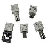
Housed Product
BOTTOM VIEW
PIN
1
3
4
5
7
8
2
6
1
2
1
1
2
1
FUNCTION
NC
SIGNAL
V
NC
NC
V
V
NC
EE
CC
EE
4 5
3
2
1
6
7
8
NOTES:
1. PINS 1, 4, 5 AND 8 ARE ISOLATED
2. PINS 3 AND 7 ARE ELECTRICALLY
PIN 1 INDICATOR
2
3 & 7
6
FROM THE INTERNAL CIRCUITRY,
BUT ARE CONNECTED TO EACH OTHER.
CONNECTED TO THE HEADER.
V
ANALOG SIGNAL
V
cc
EE
Related parts for HFBR-0410
Image
Part Number
Description
Manufacturer
Datasheet
Request
R

Part Number:
Description:
Fiber Optic Transmitters, Receivers, Transceivers 1300nm 155MBd 16-pin DIP ST Rx
Manufacturer:
Avago Technologies US Inc.

Part Number:
Description:
FIBER OPTIC TX 125 MBD 650N
Manufacturer:
Avago Technologies US Inc.
Datasheet:

Part Number:
Description:
Fiber Optic Evaluation Kit
Manufacturer:
Avago Technologies US Inc.
Datasheet:

Part Number:
Description:
RECEIVER FIBER OPTIC ST 266MBD
Manufacturer:
Avago Technologies US Inc.
Datasheet:

Part Number:
Description:
RCVR OPT HI SPEED VERS LINK HORZ
Manufacturer:
Avago Technologies US Inc.
Datasheet:

Part Number:
Description:
RCVR OPT HI SPEED VERS LINK VERT
Manufacturer:
Avago Technologies US Inc.
Datasheet:

Part Number:
Description:
TXRX OPTICAL 850NM VCSEL MT-RJ
Manufacturer:
Avago Technologies US Inc.
Datasheet:

Part Number:
Description:
TXRX MM SFP LC CONN BAIL DELATCH
Manufacturer:
Avago Technologies US Inc.
Datasheet:

Part Number:
Description:
TXRX MMF SFP GBE/FC BAIL DELATCH
Manufacturer:
Avago Technologies US Inc.
Datasheet:

Part Number:
Description:
XMITTER FIBER OPTIC 266MBD ST
Manufacturer:
Avago Technologies US Inc.
Datasheet:

Part Number:
Description:
OPTOCOUPLER GATE DRV 2A 16-SOIC
Manufacturer:
Avago Technologies US Inc.
Datasheet:
Part Number:
Description:
OPTOCOUPLER 2CH 2.5A 16-SOIC
Manufacturer:
Avago Technologies US Inc.
Datasheet:

Part Number:
Description:
OPTOCOUPLER GATE DRV 0.4A 16SOIC
Manufacturer:
Avago Technologies US Inc.
Datasheet:

Part Number:
Description:
OPTOCOUPLER 2.0A 250KHZ 8-DIP
Manufacturer:
Avago Technologies US Inc.
Datasheet:

Part Number:
Description:
OPTOCOUPLER 2.0A 250KHZ GW 8-SMD
Manufacturer:
Avago Technologies US Inc.
Datasheet: