HFBR-0416 Avago Technologies US Inc., HFBR-0416 Datasheet - Page 19
HFBR-0416
Manufacturer Part Number
HFBR-0416
Description
KIT EVAL FIBER OPTIC 125-160MBD
Manufacturer
Avago Technologies US Inc.
Datasheet
1.HFBR-4120.pdf
(24 pages)
Specifications of HFBR-0416
Main Purpose
Interface, Fiber Optics
Embedded
No
Utilized Ic / Part
HFBR-1416, HFBR-2416
Primary Attributes
Point to Point Applications up to 155MBd
Secondary Attributes
ST Connectors
Kit Contents
Assembled PCB With HFBR-1414 Tx, HFBR-2416 Rx, Application Brief 78 And Other Literature
Tool / Board Applications
Fiber Optic Transceivers
Mcu Supported Families
HFBR-0400
Lead Free Status / RoHS Status
Contains lead / RoHS non-compliant
Lead Free Status / RoHS Status
Lead free / RoHS Compliant, Contains lead / RoHS non-compliant
Other names
516-2140
HFBR-0416
HFBR-0416


HFBR-24X2 Low-Cost 5 MBd
Receiver
Description
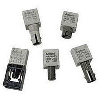
The HFBR-24X2 fiber optic
receiver is designed to operate
with the Hewlett-Packard HFBR-
14XX fiber optic transmitter and
50/125 m, 62.5/125 m, 100/
140 m, and 200 m HCS
optic cable. Consistent coupling
into the receiver is assured by the
lensed optical system (Figure 1).
Response does not vary with fiber
size
The HFBR-24X2 receiver incor-
porates an integrated photo IC
containing a photodetector and
dc amplifier driving an open-
collector Schottky output
transistor. The HFBR-24X2 is
19
Absolute Maximum Ratings
SupplyVoltage
Storage Temperature
Operating Temperature
Lead Soldering Cycle
Output Current
Output Voltage
Output Collector Power Dissipation
Fan Out (TTL)
Parameter
0.100 m.
®
fiber
Temp.
Time
designed for direct interfacing to
popular logic families. The
absence of an internal pull-up
resistor allows the open-collector
output to be used with logic
families such as CMOS requiring
voltage excursions much higher
than V
Both the open-collector “Data”
output Pin 6 and V
referenced to “Com” Pin 3, 7. The
“Data” output allows busing,
strobing and wired “OR” circuit
configurations. The transmitter is
designed to operate from a single
+5 V supply. It is essential that a
bypass capacitor (0.1 F
ceramic) be connected from
Pin 2 (V
common) of the receiver.
CC
CC
.
Symbol
T
T
V
I
V
P
N
O
) to Pin 3 (circuit
CC
O
O AV
S
A
CC
Pin 2 are
Min.
-55
-40
-0.5
-0.5
+85
+85
7.0
25
40
Max.
+260
10
18.0
5
Housed Product
Unhoused Product
Units
sec
V
mA
V
mW
C
C
C
PIN FUNCTION
1
2
3
4
V
COMMON
DATA
COMMON
CC
(5 V)
Reference
Note 1
Note 2
Related parts for HFBR-0416
Image
Part Number
Description
Manufacturer
Datasheet
Request
R

Part Number:
Description:
Fiber Optic Transmitters, Receivers, Transceivers 1300nm 155MBd 16-pin DIP ST Rx
Manufacturer:
Avago Technologies US Inc.

Part Number:
Description:
FIBER OPTIC TX 125 MBD 650N
Manufacturer:
Avago Technologies US Inc.
Datasheet:

Part Number:
Description:
Fiber Optic Evaluation Kit
Manufacturer:
Avago Technologies US Inc.
Datasheet:

Part Number:
Description:
RECEIVER FIBER OPTIC ST 266MBD
Manufacturer:
Avago Technologies US Inc.
Datasheet:

Part Number:
Description:
RCVR OPT HI SPEED VERS LINK HORZ
Manufacturer:
Avago Technologies US Inc.
Datasheet:

Part Number:
Description:
RCVR OPT HI SPEED VERS LINK VERT
Manufacturer:
Avago Technologies US Inc.
Datasheet:

Part Number:
Description:
TXRX OPTICAL 850NM VCSEL MT-RJ
Manufacturer:
Avago Technologies US Inc.
Datasheet:

Part Number:
Description:
TXRX MM SFP LC CONN BAIL DELATCH
Manufacturer:
Avago Technologies US Inc.
Datasheet:

Part Number:
Description:
TXRX MMF SFP GBE/FC BAIL DELATCH
Manufacturer:
Avago Technologies US Inc.
Datasheet:

Part Number:
Description:
XMITTER FIBER OPTIC 266MBD ST
Manufacturer:
Avago Technologies US Inc.
Datasheet:

Part Number:
Description:
OPTOCOUPLER GATE DRV 2A 16-SOIC
Manufacturer:
Avago Technologies US Inc.
Datasheet:
Part Number:
Description:
OPTOCOUPLER 2CH 2.5A 16-SOIC
Manufacturer:
Avago Technologies US Inc.
Datasheet:

Part Number:
Description:
OPTOCOUPLER GATE DRV 0.4A 16SOIC
Manufacturer:
Avago Technologies US Inc.
Datasheet:

Part Number:
Description:
OPTOCOUPLER 2.0A 250KHZ 8-DIP
Manufacturer:
Avago Technologies US Inc.
Datasheet:

Part Number:
Description:
OPTOCOUPLER 2.0A 250KHZ GW 8-SMD
Manufacturer:
Avago Technologies US Inc.
Datasheet: