IS-DEV KIT-5C NKK Switches, IS-DEV KIT-5C Datasheet - Page 18
IS-DEV KIT-5C
Manufacturer Part Number
IS-DEV KIT-5C
Description
SMARTSWITCH DEVELOPMENT KIT 5C
Manufacturer
NKK Switches
Series
SmartSwitch™r
Datasheet
1.IS-L0251-C.pdf
(24 pages)
Specifications of IS-DEV KIT-5C
Main Purpose
Switches with Programmable Display
Utilized Ic / Part
IS15SBFP4RGB
Primary Attributes
2 LCD Switches, PC Board with Flash Memory
Secondary Attributes
Power and Programming Connections
Description/function
SMARTSWITCH Development Kit
For Use With
360-2431 - SERIAL CBL RJ11-DB9 FOR DEV KIT360-2430 - POWER SUPPLY 240VAC FOR DEV KIT360-2429 - POWER SUPPLY 120VAC FOR DEV KIT
Lead Free Status / RoHS Status
Not applicable / Not applicable
Embedded
-
Lead Free Status / Rohs Status
Lead free / RoHS Compliant
For Use With/related Products
Smart Switch - RGB
Other names
360-2327
IS-DEV KIT-4
IS-DEV KIT-4


7850 East Gelding Drive • Scottsdale, AZ 85260-3420
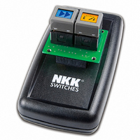
7. Hardware
Controls Overview
The Mode Select Switch has two settings; “High res” is for the LCD 64x32 (64x32) switches/ displays and
“Standard res” is for the LCD 36x24 RGB switches/ displays.
The Connector is for the installation of the Logic Boards onto the controller. One pin is keyed to reduce miss
mates.
The Batt/PWR switch has three positions: battery, off, line power.
Buzzer Volume adjusts the volume of the buzzer that activates when a button is pushed.
The 9V DC Power jack mates with a 2.5mm cylinder power connector. Center positive.
The RS232 Connector links the controller to the host.
IS-Dev Kit-5 and IS-Dev Kit-6 Users Manual A.doc
Note: Improper installation of the Logic Boards could damage either/both the Logic Board and
Toll Free 1.877.2BUYNKK (877.228.9655) • Phone 480.991.0942 • Fax 480.998.1435
RS232
IS-Dev Kit-5 and IS-Dev Kit-6 Users
www.nkkswitches.com • Email engineering@nkkswitches.com
1
2
GND
controller.
Manual
3
TX
4
RX
5
GND
6
Page 18 of 24
1209
Related parts for IS-DEV KIT-5C
Image
Part Number
Description
Manufacturer
Datasheet
Request
R

Part Number:
Description:
KIT DEV FOR LCD 64X32 SWITCH
Manufacturer:
NKK Switches
Datasheet:

Part Number:
Description:
KIT DEV LCD 64X32 COMPACT SWITCH
Manufacturer:
NKK Switches
Datasheet:

Part Number:
Description:
KIT DEV FOR OLED DISPLAY
Manufacturer:
NKK Switches
Datasheet:

Part Number:
Description:
KIT DEV FOR OLED SWITCH
Manufacturer:
NKK Switches
Datasheet:

Part Number:
Description:
BOARD DEV 2RGB SW FLASH & PROGR
Manufacturer:
NKK Switches
Datasheet:

Part Number:
Description:
KIT DEV FOR LCD 64X32 DISPLAY
Manufacturer:
NKK Switches
Datasheet:

Part Number:
Description:
SMARTSWITCH DEVELOPMENT KIT 1
Manufacturer:
NKK Switches
Datasheet:

Part Number:
Description:
SMARTSWITCH DEVELOPMENT KIT 2
Manufacturer:
NKK Switches
Datasheet:

Part Number:
Description:
SMARTSWITCH DEVELOPMENT KIT 5
Manufacturer:
NKK Switches
Datasheet:

Part Number:
Description:
SMARTSWITCH DEVELOPMENT KIT 8
Manufacturer:
NKK Switches
Datasheet:

Part Number:
Description:
LED Displays PROGRAMMABLE SWITCH
Manufacturer:
NKK Switches

Part Number:
Description:
ON-OFF PLATE - SERIES -EMP
Manufacturer:
NKK Switches
Datasheet:

Part Number:
Description:
WRENCH SOCKET FOR KB SERIES PB
Manufacturer:
NKK Switches
Datasheet:

Part Number:
Description:
SWITCH TOGGLE DPST 25A SLDR 5PCS
Manufacturer:
NKK Switches
Datasheet:

Part Number:
Description:
SWITCH TOGGLE DPDT 15A SLDR 5PC
Manufacturer:
NKK Switches
Datasheet: