EVL6563S-100W STMicroelectronics, EVL6563S-100W Datasheet - Page 33
EVL6563S-100W
Manufacturer Part Number
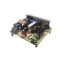
EVL6563S-100W
Description
EVAL BOARD FOR L6563(100W)
Manufacturer
STMicroelectronics
Type
Power Factor Correctionr
Specifications of EVL6563S-100W
Main Purpose
Power Management, Power Factor Correction
Embedded
No
Utilized Ic / Part
L6563
Primary Attributes
100W Power Factor Correction and Preregulator Combination
Secondary Attributes
Transition Mode & Active Tracking Boost Function.
Board Size
90 mm x 83 mm
Maximum Operating Temperature
+ 60 C
Operating Supply Voltage
90 V to 265 V
Product
Power Management Modules
Dimensions
90 mm x 83 mm
Lead Free Status / RoHS Status
Lead free / RoHS Compliant
For Use With/related Products
L6563S
Other names
497-10490


L6563S
Application information
Figure 45. Interface circuits for power up sequencing when dc-dc has the SS
function
If this is not the case or it is not possible to achieve a start-up delay long enough (because
this prevents the dc-dc stage from starting up correctly) or, simply, the PWM controller is
devoid of soft start, the arrangement of
Figure 46
lets the dc-dc converter start-up when the
voltage generated by the PFC stage reaches a preset value. The technique relies on the
UVLO thresholds of the PWM controller.
Figure 46. Interface circuits for actual power-up sequencing (master PFC)
Another possible use of the RUN and PWM_STOP pins (again, in systems where the PFC
stage is the master) is the brownout protection, thanks to the hysteresis provided.
The brownout protection is basically a not-latched device shutdown function that is activated
when a condition of mains undervoltage is detected. This condition may cause overheating
of the primary power section due to an excess of RMS current. Brownout can also cause the
PFC pre-regulator to work open loop and this could be dangerous to the PFC stage itself
and the downstream converter, should the input voltage return abruptly to its rated value.
Another problem is the spurious restarts that may occur during converter power down and
that cause the output voltage of the converter not to decay to zero monotonically. For these
reasons it is usually preferable to shutdown the unit in case of brownout.
IC shutdown upon brownout can be easily realized as shown in
Figure 47
. The scheme on
the left is of general use, that one on the right can be used if the bias levels of the multiplier
and the R
·C
time constant are compatible with the specified brownout level and with the
FF
FF
specified holdup time respectively. In this latest case, an additional resistor voltage divider
and one capacitor are not needed.
Doc ID 16116 Rev 4
33/43
Related parts for EVL6563S-100W
Image
Part Number
Description
Manufacturer
Datasheet
Request
R

Part Number:
Description:
EVAL BOARD FOR L6563(250W)
Manufacturer:
STMicroelectronics
Datasheet:

Part Number:
Description:
EVAL BOARD FOR L6563(400W)
Manufacturer:
STMicroelectronics
Datasheet:

Part Number:
Description:
Power Management Modules & Development Tools Tranisition Mode PFC L6563S EVL Board
Manufacturer:
STMicroelectronics
Datasheet:

Part Number:
Description:
EVAL BOARD L6563 (200W)
Manufacturer:
STMicroelectronics
Datasheet:
Part Number:
Description:
STMicroelectronics [RIPPLE-CARRY BINARY COUNTER/DIVIDERS]
Manufacturer:
STMicroelectronics
Datasheet:
Part Number:
Description:
STMicroelectronics [LIQUID-CRYSTAL DISPLAY DRIVERS]
Manufacturer:
STMicroelectronics
Datasheet:

Part Number:
Description:
BOARD EVAL FOR MEMS SENSORS
Manufacturer:
STMicroelectronics
Datasheet:
Part Number:
Description:
NPN TRANSISTOR POWER MODULE
Manufacturer:
STMicroelectronics
Datasheet:
Part Number:
Description:
TURBOSWITCH ULTRA-FAST HIGH VOLTAGE DIODE
Manufacturer:
STMicroelectronics
Datasheet:
Part Number:
Description:
Manufacturer:
STMicroelectronics
Datasheet:
Part Number:
Description:
DIODE / SCR MODULE
Manufacturer:
STMicroelectronics
Datasheet:
Part Number:
Description:
DIODE / SCR MODULE
Manufacturer:
STMicroelectronics
Datasheet: