CBC-EVAL-08 Cymbet Corporation, CBC-EVAL-08 Datasheet - Page 6
CBC-EVAL-08
Manufacturer Part Number
CBC-EVAL-08
Description
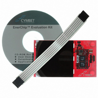
ENERCHIP EH SEH EVAL KIT
Manufacturer
Cymbet Corporation
Series
EnerChip™ EHr
Type
Energy Harvestingr
Specifications of CBC-EVAL-08
Main Purpose
Power Management, Renewable Energy
Embedded
No
Utilized Ic / Part
CBC5300
Primary Attributes
Thin Film Rechargeable Solid State Battery
Secondary Attributes
Solar Energy Harvester
Input Voltage
4.06 V
Output Voltage
3.55 V
Board Size
90.2 mm x 50.8 mm
Maximum Operating Temperature
+70 C
Minimum Operating Temperature
0 C
Product
Power Management Modules
Dimensions
90.2 mm x 50.8 mm
Lead Free Status / RoHS Status
Request inventory verification / Request inventory verification
Lead Free Status / RoHS Status
Lead free / RoHS Compliant, Request inventory verification / Request inventory verification
Other names
859-1002
Available stocks
Company
Part Number
Manufacturer
Quantity
Price
Company:

Part Number:
CBC-EVAL-08
Manufacturer:
Cymbet
Quantity:
135


EnerChip Solar Energy Harvesting Demo Kit
Again, Vmin and Vmax are functions of the EnerChip voltage and the circuit operating specifications. EnerChip
resistance varies according to temperature and state-of-charge as described above. Worst-case conditions
are often applied to the calculations to ensure proper system operation over temperature extremes, EnerChip
condition, capacitance tolerance, etc.
The composite resistance of the 2-cell parallel EnerChip arrangement on the CBC-EVAL-08 board ranges from
375Ω to about 1000Ω. At the output stage, a 1000µF, low resistance capacitor in parallel with the EnerChips
delivers peak power to the external circuit, which might contain a microcontroller and radio, for example. The
EnerChips deliver the lower level, continuous (average) power to the load. EnerChip electrical resistance is fairly
constant from 100% state-of-charge to about 10% state-of-charge; its internal resistance begins to increase
significantly only when the state-of-charge is reduced below approximately 10%.
A question often arises: “How many radio transmission pulses can be delivered by the two EnerChips on the
CBC5300?” The answer depends on a number of factors including the pulse current amplitude, pulse duration,
operating temperature, etc. The question will be addressed by way of example.
To extend the life of the EnerChips, assume the EnerChips will be cutoff from the load when a 50% state-of-
charge has been reached. (See the section titled Protection of EnerChip Storage Devices for a description of
how this is accomplished.) With 100µAh of combined capacity in the two EnerChips, a 50% state-of-charge is
simply 50µAh. Further, suppose each radio transmission uses 30mA for 20ms. The charge per pulse is:
30mA * 20ms = 600µA-seconds = 0.167µAh.
That amount of charge is transferred from the EnerChips into the output capacitor, which then delivers the
charge to the load at the rate demanded by the radio. On the CBC-EVAL-08, there is a series diode between the
output capacitor and the output pin (V
), resulting in a diode voltage drop that must be taken into account.
OUT2
In that scenario, 50% of the 100µAh allows 50µAh / 0.167µAh = 300 transmissions to be made if no ambient
power is available (i.e., when CHARGE is high). In this example, the background (sleep) current that is drawn
between transmissions has been neglected. Use actual power consumption numbers to arrive at the number
of transmissions available in any given application. The MCU can be programmed to utilize this information to
conserve power and maximize the service life of the EnerChips, as described in the following sections.
Protection of EnerChip Storage Devices
The CBC5300 energy harvester module contains a low voltage cutoff circuit that prevents the EnerChips from
being completely discharged - a condition that would permanently damage the storage device. The cutoff
circuit places a parasitic 800nA load on the EnerChips - a load that would discharge the two EnerChips in
approximately 125 hours, or just over 5 days. If the EnerChips are allowed to reach the cutoff voltage at such
low discharge currents, their specified cycle life will be reached after a few hundred of such deep discharge
cycles. To avoid this condition and extend the service life of the EnerChip, it is advisable to program the MCU to
count transmission cycles or elapsed time to determine when the EnerChips’ state-of-charge is approximately
50%, at which time the MCU would force itself or another system circuit element to briefly draw high power from
the CBC-EVAL-08, forcing the CBC-EVAL-08 circuit into a cutoff mode and thereby disconnecting the EnerChips
from the circuit. Drawing a brief burst of a few milli-Amperes from the CBC-EVAL-08 will force the cutoff
condition to occur within a few seconds. This will ensure that the charge/discharge cycle life of the EnerChips
will be greater than 5000, as rated. To calculate the number of hours the EnerChips are capable of supplying
energy to the load, add the cutoff current to the average load current drawn by the system and divide the
sum into the combined 100µAh capacity of the two EnerChips. The quotient is the number of hours until the
EnerChip is totally depleted. Divide that number in half to reach the 50% depth-of-discharge time.
©2009 Cymbet Corporation • Tel: +1-763-633-1780 • www.cymbet.com
DS-72-08 Rev18
Page 6 of 11
Related parts for CBC-EVAL-08
Image
Part Number
Description
Manufacturer
Datasheet
Request
R

Part Number:
Description:
ENERCHIP CC EVAL KIT
Manufacturer:
Cymbet Corporation
Datasheet:

Part Number:
Description:
ENERCHIP CC SEH EVAL KIT
Manufacturer:
Cymbet Corporation
Datasheet:

Part Number:
Description:
ENERCHIP EP ENERGY HARVEST EVAL
Manufacturer:
Cymbet Corporation
Datasheet:

Part Number:
Description:
INDUCTIVE CHARGING EVAL KIT
Manufacturer:
Cymbet Corporation
Datasheet:

Part Number:
Description:
LCD Graphic Display Modules & Accessories GEMboard Display Driver Board
Manufacturer:
Amulet Technologies LLC
Datasheet:

Part Number:
Description:
ENERCHIP CC EVAL KIT
Manufacturer:
Cymbet Corporation
Datasheet:
Part Number:
Description:
ENERCHIP CC SEH EVAL KIT
Manufacturer:
Cymbet Corporation
Datasheet:
Part Number:
Description:
ENERCHIP EP ENERGY HARVEST EVAL
Manufacturer:
Cymbet Corporation
Datasheet: