Z8FMC160100KIT Zilog, Z8FMC160100KIT Datasheet - Page 320
Z8FMC160100KIT
Manufacturer Part Number
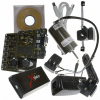
Z8FMC160100KIT
Description
KIT DEV FOR Z8 ENCORE Z8FMC16100
Manufacturer
Zilog
Series
Z8 Encore! MC™r
Datasheets
1.Z8FMC160100KIT.pdf
(7 pages)
2.Z8FMC160100KIT.pdf
(383 pages)
3.Z8FMC160100KIT.pdf
(20 pages)
Specifications of Z8FMC160100KIT
Main Purpose
Power Management, Motor Control
Embedded
Yes, MCU, 8-Bit
Utilized Ic / Part
Z8FMC16100
Primary Attributes
3-Ph DC Motors
Secondary Attributes
Graphic User Interface
Processor To Be Evaluated
Z8FMC16100
Data Bus Width
8 bit
Interface Type
USB
For Use With
269-4664 - KIT ACC OPTO-ISO USB SMART CABLE269-4661 - KIT ACC ETHERNET SMART CABLE269-4539 - KIT ACCESSORY USB SMART CABLE
Lead Free Status / RoHS Status
Contains lead / RoHS non-compliant
Other names
269-3639


PS024613-0910
Bit
Position
[5–3]
PRES
Value (H) Description
000
001
010
100
101
011
110
111
The timer input clock is divided by 2
The prescaler is reset each time the Timer is disabled. This insures proper clock
division each time the Timer is restarted.
Divide by 1
Divide by 2
Divide by 4
Divide by 8
Divide by 16
Divide by 32
Divide by 64
Divide by 128
(Continued)
PWM DUAL OUTPUT mode–If enabled, the Timer Output is set=TPOL after
PWM match and set=TPOL after Reload. If enabled the Timer Output
Complement takes on the opposite value of the Timer Output. The PWMD field
in the T0CTL1 register determines an optional added delay on the assertion
(Low to High) transition of both Timer Output and the Timer Output
Complement for deadband generation.
CAPTURE RESTART mode–If the timer is enabled the Timer Output signal is
complemented after timer Reload.
0 = Count is captured on the rising edge of the Timer Input signal.
1 = Count is captured on the falling edge of the Timer Input signal.
COMPARATOR COUNTER mode–If the timer is enabled the Timer Output
signal is complemented after timer Reload.
0 = Count is captured on the rising edge of the Timer Input signal.
1 = Count is captured on the falling edge of the Timer Input signal.
TRIGGERED ONE-SHOT mode–If the timer is enabled the Timer Output signal
is complemented after timer Reload.
0 = The timer triggers on a Low to High transition on the input.
1 = The timer triggers on a High to Low transition on the input.
PRES
, where PRES can be set from 0 to 7.
Z8FMC16100 Series Flash MCU
Appendix A—Register Tables
Product Specification
308
Related parts for Z8FMC160100KIT
Image
Part Number
Description
Manufacturer
Datasheet
Request
R

Part Number:
Description:
Communication Controllers, ZILOG INTELLIGENT PERIPHERAL CONTROLLER (ZIP)
Manufacturer:
Zilog, Inc.
Datasheet:

Part Number:
Description:
KIT DEV FOR Z8 ENCORE 16K TO 64K
Manufacturer:
Zilog
Datasheet:

Part Number:
Description:
KIT DEV Z8 ENCORE XP 28-PIN
Manufacturer:
Zilog
Datasheet:

Part Number:
Description:
DEV KIT FOR Z8 ENCORE 8K/4K
Manufacturer:
Zilog
Datasheet:

Part Number:
Description:
KIT DEV Z8 ENCORE XP 28-PIN
Manufacturer:
Zilog
Datasheet:

Part Number:
Description:
DEV KIT FOR Z8 ENCORE 4K TO 8K
Manufacturer:
Zilog
Datasheet:
Part Number:
Description:
CMOS Z8 microcontroller. ROM 16 Kbytes, RAM 256 bytes, speed 16 MHz, 32 lines I/O, 3.0V to 5.5V
Manufacturer:
Zilog, Inc.
Datasheet:
Part Number:
Description:
Low-cost microcontroller. 512 bytes ROM, 61 bytes RAM, 8 MHz
Manufacturer:
Zilog, Inc.
Datasheet:
Part Number:
Description:
Z8 4K OTP Microcontroller
Manufacturer:
Zilog, Inc.
Datasheet:
Part Number:
Description:
CMOS SUPER8 ROMLESS MCU
Manufacturer:
Zilog, Inc.
Datasheet:
Part Number:
Description:
SL1866 CMOSZ8 OTP Microcontroller
Manufacturer:
Zilog, Inc.
Datasheet:
Part Number:
Description:
SL1866 CMOSZ8 OTP Microcontroller
Manufacturer:
Zilog, Inc.
Datasheet:
Part Number:
Description:
OTP (KB) = 1, RAM = 125, Speed = 12, I/O = 14, 8-bit Timers = 2, Comm Interfaces Other Features = Por, LV Protect, Voltage = 4.5-5.5V
Manufacturer:
Zilog, Inc.
Datasheet:
Part Number:
Description:
Manufacturer:
Zilog, Inc.
Datasheet: