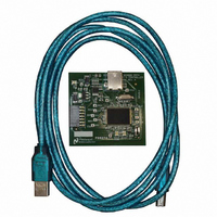
SPUSI2/NOPB National Semiconductor, SPUSI2/NOPB Datasheet

SPUSI2/NOPB
Specifications of SPUSI2/NOPB
Available stocks
Related parts for SPUSI2/NOPB
SPUSI2/NOPB Summary of contents
Page 1
... Sensor Signal Path Control Panel © 2009 National Semiconductor Corporation. Software Manual June 2009 Rev - 1.1 ...
Page 2
... Sensor Signal Path Control Panel Software Manual 1 Introduction. This document explains how to use the National Semiconductor Sensor Signal Path Control Panel software, referred to as SCP in this document. The SCP software allows a system designer to evaluate the signal path performance of various sensor boards such as the Differential Sensor, Photo Diode, Thermocouple, and Thermopile Boards using the SPUSI2 Data Capture Board ...
Page 3
Installation recommended that you completely update your Windows XP and then run NscSVCPinstall.exe. This ensures that you have all the latest changes and patches. Installing a new SCP version automatically replaces an existing older version. The SCP ...
Page 4
This optional prompt is followed by a board name query: After the board has been identified, the corresponding board configuration script is loaded and the Sensor Signal Path Control Panel is brought up on the screen. The SP1202S01RB Control Panel ...
Page 5
The top portion of the panel provides access to the configuration corresponding to the channel selected in the Channel # window in the top middle of the control panel. The lower portion of the panel provides the sensor measurements for ...
Page 6
All channel specific actions such as Configuration Panel settings and calibration correspond to the selected channel. The term current channel is also used in this document to refer to this selected channel. 3.1.2 Channel Enable. Any present channel pane may ...
Page 7
Computations generally use either the sensitivity value or an endpoint calibration, whichever is provided last. A user entered sensitivity value is ignored if the user calibrates the board and switches to using calibration based computations. The sensitivity units window is ...
Page 8
Rf. The Rf resistance value is used for applications such as the Photo Diode Sensor Board. 3.2.7 ADC Resolution. This selects the ADC resolution in bits which is used for computations. Figure 3-8: ADC resolution selection in number of ...
Page 9
Channel Sensor Measurements. The lower portion of the Control Panel displays the channel sensor measurements for enabled channels when the MEASURE button is selected. It also has three buttons which control the panel behavior. Figure 4-1: Sensor Measurements Panel. ...
Page 10
Channel State Indicator Colors. The color indicator in the lower center of the channel pane indicates the channel state. A gray indicator corresponds to a disabled or absent channel. A green indicator corresponds to a channel with valid measurements. ...
Page 11
The button normally reads RECORD but changes to PAUSE while recording. It may then be used to PAUSE the recording. The button changes to RESUME while paused and may be used to resume the recording. Note that the pause behavior ...
Page 12
Calibrating End Points. To calibrate the sensor to reference end points, first select the proper units in the calibrate window. Then enter the expected sensor value, such as degrees or inches, from an independent reference measurement. corresponding button to ...
Page 13
SensorIn = As an example, assume the user reads the codes 2433 and 2133, corresponding to 15 and 35 degrees, respectively (35-15) / (2433 - 2163) = -1/35 = -0.074 – (-1/35) (2433) ...
Page 14
Figure 5-3: Selecting between Average and Immediate display types. 5.1.2 Display Format. The display format can either be the simple sensor code values, the sensor mV values, ...
Page 15
Figure 5-6: Save Configuration in file. Note that the saved scripts are very verbose as they list almost all the channels individually and contain definitions for all the Channel-Variables. Similarly the Load command also prompts the user for a text ...
Page 16
About. The About selection displays a window with the current software and hardware versions. 5.5 Exit. The right most menu selection is Exit. The application may be terminated by selecting this or by closing the window with the X ...
Page 17
Channel Code. All measurements begin with a channel code consisting of the ADC resolution, the number of bits supported by the board sensor. The user may select to reduce the resolution to evaluate the computations with a lower resolution. ...
Page 18
Board Specific Computations. The generic computations have been derived to support as many boards as possible by providing different variable values and are a superset of the corresponding individual board equations. By setting non-relevant variables to passive values, such ...
Page 19
Appendix 1.0 SPUSI2 Setup Procedure. 1. Download Sensor Path Control Panel Software onto your computer prior to connecting board to computer. 2. Connect board to computer. The Found New Hardware Wizard will popup. Select Yes, this time only and click ...
Page 20
Wizard begins to install software for Sensor Signal Path 2008 Board. Click Continue Anyway on the Hardware Installation pop-up. 5. Click Finish. ...
Page 21
...


