SPUSI2/NOPB National Semiconductor, SPUSI2/NOPB Datasheet - Page 11
SPUSI2/NOPB
Manufacturer Part Number
SPUSI2/NOPB
Description
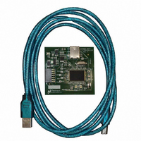
BOARD EVAL DATA CAPTURE BOARD
Manufacturer
National Semiconductor
Specifications of SPUSI2/NOPB
Main Purpose
Interface, Data Capture
Embedded
Yes, MCU, 8-Bit
Utilized Ic / Part
WEBENCH® Sensor Designer Boards
Primary Attributes
USB Interface Dongle II
Secondary Attributes
SPI Interface
Lead Free Status / RoHS Status
Lead free / RoHS Compliant
Other names
SPUSI2
Available stocks
Company
Part Number
Manufacturer
Quantity
Price
Company:

Part Number:
SPUSI2/NOPB
Manufacturer:
National Semiconductor
Quantity:
135


It may then be used to PAUSE the recording. The button changes to RESUME
while paused and may be used to resume the recording.
the button will then simply indicate that you can stop recording. If you stop
recording in this mode all values are discarded when recording is stopped before
completion.
controlled independently.
measurements are started or stopped.
measurements are stopped, the following message is shown to the user:
4.2.3 Calibrate Button.
channel which is used to enter the calibration data end points. The computations
use either calibration points or theoretical values as selected in the configuration
panel.
data points in the desired range. Calibration consists of setting the sensor to
known values and capturing the output code. To calibrate the selected channel
click on the CALIBRATE button in the lower left part of the pane. This opens the
corresponding window shown in the figure below.
user entered physical sensor values. These are used as two data points to
compute the slope and intercept for linear extrapolation.
The window changes to the current properties after the user enters a data point.
The button normally reads RECORD but changes to PAUSE while recording.
Note that the pause behavior may not be allowed on all applications and
The Record operation requires channel measurements but may be
The center button is used to bring up the calibrate panel for the current
For best results, the sensor should be calibrated using the two segment
The calibration information consists of two sensor code values along with
The initial window shows the current calibration properties if they are valid.
Figure 4-6: Message indicating record enabled during stopped measurements.
Figure 4-7: Calibration Window with previous Data Points in Display.
Figure 4-5: Record Button when pause is not allowed.
Recording automatically starts and stops when
If recording is enabled when
Related parts for SPUSI2/NOPB
Image
Part Number
Description
Manufacturer
Datasheet
Request
R

Part Number:
Description:
National Semiconductor [8-Bit D/A Converter]
Manufacturer:
National Semiconductor
Datasheet:
Part Number:
Description:
National Semiconductor [Media Coprocessor]
Manufacturer:
National Semiconductor
Datasheet:
Part Number:
Description:
Digitally Controlled Tone and Volume Circuit with Stereo Audio Power Amplifier, Microphone Preamp Stage and National 3D Sound
Manufacturer:
National Semiconductor
Datasheet:
Part Number:
Description:
Digitally Controlled Tone and Volume Circuit with Stereo Audio Power Amplifier, Microphone Preamp Stage and National 3D Sound
Manufacturer:
National Semiconductor
Datasheet:
Part Number:
Description:
AC97 Rev 2 Codec with Sample Rate Conversion and National 3D Sound
Manufacturer:
National Semiconductor
Part Number:
Description:
Manufacturer:
National Semiconductor
Datasheet:
Part Number:
Description:
Manufacturer:
National Semiconductor
Datasheet:
Part Number:
Description:
General Purpose, Low Voltage, Low Power, Rail-to-Rail Output Operational Amplifiers
Manufacturer:
National Semiconductor
Datasheet:
Part Number:
Description:
8-bit 20 MSPS flash A/D converter.
Manufacturer:
National Semiconductor
Datasheet:
Part Number:
Description:
Low Noise Quad Operational Amplifier
Manufacturer:
National Semiconductor
Datasheet:
Part Number:
Description:
Quad Differential Line Receivers
Manufacturer:
National Semiconductor
Datasheet:
Part Number:
Description:
Quad High Speed Trapezoidal? Bus Transceiver
Manufacturer:
National Semiconductor
Datasheet:
Part Number:
Description:
Dual Line Receiver
Manufacturer:
National Semiconductor
Datasheet:
Part Number:
Description:
TTL to 10k ECL Level Translator with Latch
Manufacturer:
National Semiconductor
Datasheet: