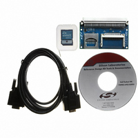
USB-MSD-RD Silicon Laboratories Inc, USB-MSD-RD Datasheet - Page 6

USB-MSD-RD
Manufacturer Part Number
USB-MSD-RD
Description
KIT REF DES USB MASS STORAGE
Manufacturer
Silicon Laboratories Inc
Specifications of USB-MSD-RD
Main Purpose
Memory, USB Mass Storage
Embedded
Yes, MCU, 8-Bit
Utilized Ic / Part
C8051F340-DK
Primary Attributes
Supports CF SD & MMC Cards,
Secondary Attributes
Requires C8051F340DK Development Kit
Interface Type
RS-232
Operating Supply Voltage
50 V
Product
Interface Modules
For Use With/related Products
C8051F340
Lead Free Status / RoHS Status
Contains lead / RoHS non-compliant
Lead Free Status / RoHS Status
Lead free / RoHS Compliant, Contains lead / RoHS non-compliant
Other names
336-1320
USB-MSD-RD
5. USB MSD Reference Design Kit Demonstration
The following step-by-step demonstration will walk you through the various features and capabilities of this
reference design. There are three parts to this demonstration: Firmware Download, Example Application
Demonstration, and Mass Storage Device Demonstration.
Note: The demonstration instructions assume that a PC running Windows 2000/XP/Server2003 is being used.
5.1. Firmware Download
The steps in this section will guide you in downloading the USB MSD Reference Design firmware to the
C8051F340-TB target board.
1. Follow the 'Software Setup' instructions in the C8051F340DK User's Guide to install the Silicon Laboratories
2. Depending on which type of debug adapter you have, set up the hardware as shown in one of the two diagrams
3. Launch the Silicon Labs IDE using the icon from your Start Menu: 'Start Menu
4. Before connecting to the target device, several connection options may need to be set. Open the 'Connection
6
IDE. This document is available at the following web page:
web_content/products/Microcontrollers/USB/en/C8051F340DK.htm.
below (Figure 5, Figure 6). Consult the C8051F340DK User's Guide for detailed instructions.
Laboratories
Options' window by selecting 'Options
was included with the kit in the "Serial Adapter" section. Next, the correct "Debug Interface" must be selected.
C8051F34x family devices use the Silicon Labs 2-wire (C2) debug interface. Once these selections are made,
click the OK button to close the window.
PC
PC
USB Port
Serial Port
→
Silicon Laboratories IDE'
Figure 5. Hardware Setup using a Serial Debug Adapter
Figure 6. Hardware Setup using a USB Debug Adapter
Cable
USB
Cable
Serial
→
Connection Options...' in the IDE menu. First, select the adapter that
Adapter
Adapter
Debug
Serial
USB
Rev. 0.1
Adapter
AC/DC
Adapter
AC/DC
Ribbon Cable
http://www.silabs.com/tgwWebApp/public/
Ribbon
Cable
→
Programs
Target Board
Target
Board
→
Silicon


