EVB-USB2524 SMSC, EVB-USB2524 Datasheet - Page 13
EVB-USB2524
Manufacturer Part Number
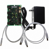
EVB-USB2524
Description
BOARD EVAL USB2524 SHARE/SWITCH
Manufacturer
SMSC
Series
MultiSwitch™r
Specifications of EVB-USB2524
Main Purpose
Interface, USB 2.0 Hub
Embedded
No
Utilized Ic / Part
USB2524
Primary Attributes
Quad Port Hub, High Speed (480Mbps), SMBus
Secondary Attributes
Overcurrent Protection, Port Power Switching, Multi-TT Enabled
Interface Type
USB
Operating Supply Voltage
5 V
Product
Interface Modules
Lead Free Status / RoHS Status
Lead free / RoHS Compliant
For Use With/related Products
USB2524
Other names
638-1044
Available stocks
Company
Part Number
Manufacturer
Quantity
Price
Company:

Part Number:
EVB-USB2524
Manufacturer:
SMSC
Quantity:
135


USB MultiSwitch
Datasheet
SMSC USB2524
Polarity strapping
USB Transceiver
Port [2:1] Green
strapping option
Enhanced Port
LED Indicators
Over Current
Removable
Port Power
Port Non-
NAME
Sense
LED
Bias
&
TM
Hub
NON_REM[1:0]
PRTPWR_POL
LED_A[2:1]_N/
LED_B[4:1]_N
OCS[4:1]_N
SYMBOL
RBIAS
Table 4.1 Switching Hub Pin Descriptions (continued)
TYPE
I/O12
I/O12
IPU
I/O
I-R
DATASHEET
Green indicator LED for ports 2 and 1. Will be active low
when LED support is enabled via EEPROM or SMBus.
If the hub is configured by the internal default configuration,
these pins will be sampled at RESET_N negation to
determine if ports [3:1] contain permanently attached (non-
removable) devices. Also, the active state of the LED's will
be determined as follows:
NON_REM[1:0] = '00', All ports are removable,
LED_A2_N is active high,
LED_A1_N is active high.
NON_REM[1:0] = '01', Port 1 is non-removable,
LED_A2_N is active high,
LED_A1_N is active low.
NON_REM[1:0] = '10', Ports 1 & 2 are non-removable,
LED_A2_N is active low,
LED_A1_N is active high.
NON_REM[1:0] = '11', Ports 1, 2, & 3 are non-removable,
LED_A2_N is active low,
LED_A1_N is active low.
These 4 pins in conjunction with the LED_A[4:1]_N pins
provides a total of 8 LED pins which are used to indicate
upstream host ownership of the downstream ports.
2 operational modes are available
Single Color LED Mode: LED will light to show which host
owns each of the downstream ports. If a port is
“unassigned” then neither LED for that port will light up.
Dual Color LED’s: (note; 4 possible states are displayed to
the user, Green, Red, Orange and Off).
Port Power Polarity strapping determination for the active
signal polarity of the PRTPWR[4:1] pins.
While RESET_N is asserted, the logic state of this pin will
(through the use of internal combinatorial logic) determine
the active state of the PRTPWR[4:1] pins in order to ensure
that downstream port power is not inadvertently enabled to
inactive ports during a hardware reset.
When RESET_N is negated, the logic value will be latched
internally, and will retain the active signal polarity for the
PRTPWR[4:1] pins.
‘1’ = PRTPWR[4:1] pins have active ‘high’ polarity
‘0’ = PRTPWR[4:1] pins have active ‘low’ polarity
Warning: Active Low port power controllers may glitch
the downstream port power when system power is first
applied. Care should be taken when designing with
active low components!
Input from external current monitor indicating an over-
current condition. {Note: Contains internal pull-up to 3.3V
supply}
A 12.0kΩ (+/− 1%) resistor is attached from ground to this
pin to set the transceiver’s internal bias settings.
13
FUNCTION
Revision 1.91 (08-22-07)
Related parts for EVB-USB2524
Image
Part Number
Description
Manufacturer
Datasheet
Request
R

Part Number:
Description:
BOARD EVAL FOR USB2514 48-QFN
Manufacturer:
SMSC
Datasheet:

Part Number:
Description:
Networking Modules & Development Tools LAN7500 USB 2.0 BRD 10/100/1000 GigB
Manufacturer:
SMSC
Datasheet:

Part Number:
Description:
BOARD EVAL FOR USB2514/USB2514I
Manufacturer:
SMSC
Datasheet:

Part Number:
Description:
BOARD EVAL FOR USB2512/USB2512I
Manufacturer:
SMSC
Datasheet:

Part Number:
Description:
BOARD EVAL FOR USB2513/USB2513I
Manufacturer:
SMSC
Datasheet:

Part Number:
Description:
BOARD EVALUATION FOR EMC1043
Manufacturer:
SMSC
Datasheet:
Part Number:
Description:
EVALUATION BOARD FOR USB3311C
Manufacturer:
SMSC
Datasheet:
Part Number:
Description:
EVALUATION BOARD FOR USB3317C
Manufacturer:
SMSC
Datasheet:

Part Number:
Description:
EVALUATION BOARD USB2241-AEZG
Manufacturer:
SMSC
Datasheet:

Part Number:
Description:
BOARD EVALUATION FOR USB2502
Manufacturer:
SMSC
Datasheet:
Part Number:
Description:
BOARD EVALUATION FOR USB2504
Manufacturer:
SMSC
Datasheet:

Part Number:
Description:
EVALUATION BOARD LAN9500-ABZJ
Manufacturer:
SMSC
Datasheet:
Part Number:
Description:
Ethernet Modules & Development Tools LAN9500 Design Kit Low-Cost USB Dongle
Manufacturer:
SMSC
Datasheet:
Part Number:
Description:
Interface Modules & Development Tools Eval BRD-USB2602
Manufacturer:
SMSC
Datasheet: