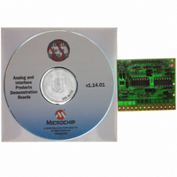
MCP4XXXDM-DB Microchip Technology, MCP4XXXDM-DB Datasheet - Page 26

MCP4XXXDM-DB
Manufacturer Part Number
MCP4XXXDM-DB
Description
BOARD DAUGHTER DIGIPOT MCP4XXX
Manufacturer
Microchip Technology
Datasheet
1.MCP4XXXDM-DB.pdf
(38 pages)
Specifications of MCP4XXXDM-DB
Main Purpose
Digital Potentiometer
Embedded
Yes, MCU, 8-Bit
Utilized Ic / Part
MCP42010-103, MCP4021-103
Primary Attributes
2 Dual Pots and 1 Single Pot, 10 kOhm, Non Volatile
Secondary Attributes
2.7 ~ 5.5 V, 150 ppm/°C or 800 ppm/°C
Processor To Be Evaluated
MCP4xxx
Lead Free Status / RoHS Status
Not applicable / Not applicable
Lead Free Status / RoHS Status
Lead free / RoHS Compliant, Not applicable / Not applicable
Available stocks
Company
Part Number
Manufacturer
Quantity
Price
Company:
Part Number:
MCP4XXXDM-DB
Manufacturer:
MICROCHIP
Quantity:
12 000
MCP4XXX Digital Potentiometer Daughter Board User’s Guide
DS51621A-page 22
2.5.2
Table 2-3 shows the sequence of steps to demonstrate the MCP4XXXDM-DB board
(as shipped) with the PICDEM FS USB Demo Board.
TABLE 2-3:
Step Action
1
2
3
4
5
6
7
8
Note:
Connect ICD 2 to the PC and to the
PICDEM FS USB Demo Board
Power up and program the PICDEM
FS USB Demo Board with the file
“00106 - FS USB.hex”
Disconnect the ICD 2 from the
PICDEM FS USB Demo Board
Configure the MCP4XXXDM-DB to
the jumper settings shown in
Figure 2-9.
Insert the MCP4XXXDM-DB board
into the PICDEM FS USB Demo
Board J6 header. Ensure proper
orientation of Daughter Board to J6
Header.
Connect U1-P1A to the V
tion post and U1-P1B to the V
connection post.
Turn on oscilloscope and configure as
follows:
• Channel 1 to 4 @ 1V/Division
• Channel 1 to 4 have same
• Time-base = 200 ms/Division
Connect the oscilloscope probes as
follows:
• Channel 1 to the U1-P0W Pad
• Channel 2 to the U1-P1A Pad
• Channel 3 to the U1-P1B Pad
• Channel 4 to the U1-P1W Pad
Note:
ground reference point
Using the PICDEM FS USB Demo Board
For information on how to use MPLAB-IDE, ICD 2, or any other aspect of
the PICmicro Development tool platform, please refer to the appropriate
documentation.
DEMO STEPS FOR THE PICDEM FS USB DEMO BOARD
You may be required to
solder a 28-pin Female
header into the J6 header
socket.
DD
connec-
SS
Result
—
—
PICDEM FS USB Demo Board
program should now be operating
—
—
—
—
Output waveform should look similar
to Figure 2-10.
© 2006 Microchip Technology Inc.


