MCP1630RD-LIC2 Microchip Technology, MCP1630RD-LIC2 Datasheet - Page 12
MCP1630RD-LIC2
Manufacturer Part Number
MCP1630RD-LIC2
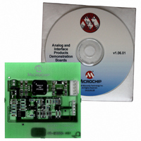
Description
BOARD DEMO FOR MCP1630 LI-ION
Manufacturer
Microchip Technology
Specifications of MCP1630RD-LIC2
Main Purpose
Power Management, Battery Charger
Embedded
Yes, MCU, 8-Bit
Utilized Ic / Part
MCP1630
Primary Attributes
3 Cells- NiMH / NiCd, 1.35A Out, 6V ~ 14 V Input
Secondary Attributes
Preconditioning, Cell Temperature & Batt Pack Fault Monitoring
Silicon Manufacturer
Microchip
Silicon Core Number
MCP1630
Features
Overvoltage/Overtemperature Protection, Over Current Protection In The Event Of A Shorted Battery
Lead Free Status / RoHS Status
Contains lead / RoHS non-compliant
Lead Free Status / RoHS Status
Lead free / RoHS Compliant, Contains lead / RoHS non-compliant


MCP1630 Li-Ion Multi-Bay Battery Charger User’s Guide
2.3
DS51515A-page 8
GETTING STARTED
The MCP1630 Li-Ion Multi-Bay Battery Charger is fully assembled and tested for
charging single-cell, Li-Ion battery packs with the recommended charge profile for
Li-Ion batteries. This board requires the use of an external input voltage source (+10V
to +28V) and external load (battery or simulated battery load). It is recommended that
a battery pack containing Microchip’s PS700 battery monitor be used to maximize the
full benefits of the pseudo-smart battery system with the shortest charge cycle times.
Alternatively, standard battery packs or the recommended simulated load can be
utilized to evaluate the system performance.
2.3.1
Powering the MCP1630 Li-Ion Multi-Bay Battery Charger
1. Apply the input voltage to the input terminal block (JP2). The input voltage source
2. Connect the positive side (+) of the input source to pin 1 of JP2. Connect the
FIGURE 2-1:
should be limited to the 0V to +28V range. For normal operation, the input voltage
should be between +10V and +28V. The input voltage must not exceed an
absolute maximum of +35V.
negative or return side (-) of the input source to pin 2 of JP2. Refer to Figure 2-1.
Input
Voltage
Power Input and Output Connections
+
–
Setup Configuration Diagram.
© 2005 Microchip Technology Inc.
B +
S DA
S C L
T E MP
B -
B +
S DA
S C L
T E MP
B -
P G C
P G D
V S S
V DD
V P P
Bay 2
Battery
Header
Bay 1
Battery
Header
Programming
Header
Related parts for MCP1630RD-LIC2
Image
Part Number
Description
Manufacturer
Datasheet
Request
R

Part Number:
Description:
REF DESIGN MCP1630 NIMH BATT CHG
Manufacturer:
Microchip Technology
Datasheet:

Part Number:
Description:
REF DESIGN MCP1630V BI-DIR 4CELL
Manufacturer:
Microchip Technology
Datasheet:

Part Number:
Description:
REFERENCE DESIGN FOR MCP1630
Manufacturer:
Microchip Technology
Datasheet:

Part Number:
Description:
MCP1630 Dual Synchronous Buck Regulator Demo Board DEVTOOL - Analog
Manufacturer:
Microchip Technology
Datasheet:
Part Number:
Description:
Power Management IC Development Tools MCP1630 Sepic Automotive LED Drvr
Manufacturer:
Microchip Technology
Datasheet:

Part Number:
Description:
Manufacturer:
Microchip Technology Inc.
Datasheet:
Part Number:
Description:
Manufacturer:
Microchip Technology Inc.
Datasheet:
Part Number:
Description:
Manufacturer:
Microchip Technology Inc.
Datasheet:
Part Number:
Description:
Manufacturer:
Microchip Technology Inc.
Datasheet:
Part Number:
Description:
Manufacturer:
Microchip Technology Inc.
Datasheet:
Part Number:
Description:
Manufacturer:
Microchip Technology Inc.
Datasheet: