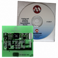
MCP1630RD-LIC2 Microchip Technology, MCP1630RD-LIC2 Datasheet - Page 13

MCP1630RD-LIC2
Manufacturer Part Number
MCP1630RD-LIC2
Description
BOARD DEMO FOR MCP1630 LI-ION
Manufacturer
Microchip Technology
Specifications of MCP1630RD-LIC2
Main Purpose
Power Management, Battery Charger
Embedded
Yes, MCU, 8-Bit
Utilized Ic / Part
MCP1630
Primary Attributes
3 Cells- NiMH / NiCd, 1.35A Out, 6V ~ 14 V Input
Secondary Attributes
Preconditioning, Cell Temperature & Batt Pack Fault Monitoring
Silicon Manufacturer
Microchip
Silicon Core Number
MCP1630
Features
Overvoltage/Overtemperature Protection, Over Current Protection In The Event Of A Shorted Battery
Lead Free Status / RoHS Status
Contains lead / RoHS non-compliant
Lead Free Status / RoHS Status
Lead free / RoHS Compliant, Contains lead / RoHS non-compliant
TABLE 2-1:
© 2005 Microchip Technology Inc.
STATUS OUTPUT
Apply the load to a battery header.
1. To apply a load to the MCP1630 Li-Ion Multi-Bay Battery Charger, the positive
2. A thermistor referenced to B- in the battery pack should be utilized. If a thermistor
3. SMBus interface connections are provided at the battery headers for communi-
4. The code will prevent the board from entering the 2A Fast Charge mode if the
FIGURE 2-2:
Status LEDs
1. Each charger bay has a LED to indicate charge status (D8 for charge bay 1 and
Programming
1. Header JP4 is provided for in-system circuit programming.
Qualification
Preconditioning
Constant Current Fast Charge
Constant Voltage
Charge Complete
Safety Timer Fault
Cell Temperature Invalid
Battery Disconnected
Input Power Removed
side of the load (B+) should be connected to pin 1 of JP1 or JP3. The negative
side of the load (B-) should be connected to pin 5 of JP1 or JP3. Care should be
taken when using either electronic loads or ground-referenced loads.
is not available or desired, a 10 kΩ resistor should be placed between pin 4 and
pin 5 of the battery header. Alternatively, the firmware can be modified to ignore
the thermistor input.
cation with battery packs containing Microchip’s PS700. Utilizing a pseudo-smart
battery system will provide reduced charge cycle times by compensating for IR
voltage drops in the high-current charge path.
battery terminal voltage is less than 2.8V. During power-up, the board will always
trickle charge first, so using a purely resistive load will not work for trickle and fast
charge current. The best way to evaluate the charger is to use a single-cell, Li-Ion
battery pack or the reccomended simulated battery load. Refer to Figure 2-2.
D6 for charge bay 2), as well as a LED to indicate a fault (D4 for charge bay 1
and D5 for charge bay 2).
CHARGE CYCLE STATE
B +
B –
+
–
Simulated Battery Load.
1,000 µF
10V Al
Installation and Operation
(0.5 Hz, 50% duty cycle)
(0.5 Hz, 50% duty cycle)
STATUS (GREEN)
2Ω
5W
Flashing
Flashing
OFF
OFF
OFF
ON
ON
ON
ON
1Ω
1W
+
–
Variable
Power Supply
0V - 6V
FAULT (RED)
DS51515A-page 9
OFF
OFF
OFF
OFF
OFF
ON
ON
ON
ON


