MCP215XDM Microchip Technology, MCP215XDM Datasheet - Page 20
MCP215XDM
Manufacturer Part Number
MCP215XDM
Description
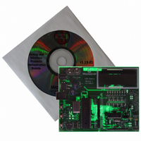
BOARD DEMO FOR MCP215X
Manufacturer
Microchip Technology
Specifications of MCP215XDM
Main Purpose
Interface, IrDA
Embedded
Yes, MCU, 8-Bit
Utilized Ic / Part
MCP2150, MCP2155
Primary Attributes
IrDA Controller with PIC18F MCU
Secondary Attributes
Set up as a Data Logger with LCD, GUI, Socket for EEPROM, Battery Powerable
Processor To Be Evaluated
MCP2150
Silicon Manufacturer
Microchip
Silicon Core Number
MCP2150, MCP2155
Kit Application Type
Interface
Application Sub Type
Standard Protocol Stack Controller
Kit Contents
Board
Rohs Compliant
Yes
Lead Free Status / RoHS Status
Lead free / RoHS Compliant
Lead Free Status / RoHS Status
Lead free / RoHS Compliant, Lead free / RoHS Compliant
Other names
MCP215XDMR
MCP215XDMR
MCP215XDMR
Available stocks
Company
Part Number
Manufacturer
Quantity
Price
Company:

Part Number:
MCP215XDM
Manufacturer:
MICROCHIP
Quantity:
12 000


TABLE 2-1:
DS51516B-page 16
Legend: S = Jumper is shorted (Closed)
Note 1:
Jumper
JP1C1
JP2C1
JP1A1
JP2A1
JP1B1
JP2B1
JMP1
JMP2
JMP3
JP1
JP3
J7
#
1-2 = Pins 1 and 2 are shorted together
2-3 = Pins 2 and 3 are shorted together
Settings
Typical
This is the default jumper settings for MCP215X/40 Data Logger Demo Board as shipped.
2-3
2-3
2-3
(1)
O
O
O
O
O
O
S
S
S
JUMPER DESCRIPTIONS AND SETTINGS
Selects the Source of the MCP215X/40 devices
BAUD0/RXPDREF pin
1-2 = RXPDREF signal connected to BAUD0/RXPDREF pin
2-3 = BAUD0 signal connected to BAUD0/RXPDREF pin
Selects the Source of the MCP215X/40 devices
BAUD1/RXPD pin
1-2 = RXPD signal connected to BAUD1/RXPD pin
2-3 = BAUD1 signal connected to BAUD1/RXPD pin
Selects the Function of the MCP215X/40 devices
RXIR/PHACT pin
1-2 = RXIR/PHACT pin drives PHACT signal (for LED)
2-3 = RXIR signal connected to RXIR/PHACT pin
To connect cathode of LEDs (RD7:RD0) to V
S = Cathode of LEDs to V
O = Cathode of LEDs floating
To connect EN of MCP2150 to V
S = MCP2150 in Low-power mode
O = MCP2150 during normal operation
Connects RC source to PIC MCU clock input
S = RC is connected to PIC MCU
O = RC is NOT connected to PIC MCU
Connects the Optical Transceivers (HSDL-3000) RXD sig-
nal to jumpers JMP2 and JMP3.
S = RXD connected to JMP pin 1 and JMP3 pin 1
O = RXD Not connected to JMP pin 1 and JMP3 pin 1
Connects the Optical Transceivers (HSDL-3000) TXD signal
to the MCP215X/40
S = TXD connected to TXIR
O = TXD Not connected to TXIR
Connects the Optical Transceivers (TFDU-4100) RXD
signal to jumpers JMP2 and JMP3.
S = RXD connected to JMP pin 1 and JMP3 pin 1
O = RXD Not connected to JMP pin 1 and JMP3 pin 1
Connects the Optical Transceivers (TFDU-4100) TXD signal
to the MCP215X/40
S = TXD connected to TXIR
O = TXD Not connected to TXIR
Connects the Optical Transceivers (TFDU-4300) RXD
signal to jumpers JMP2 and JMP3.
S = RXD connected to JMP pin 1 and JMP3 pin 1
O = RXD Not connected to JMP pin 1 and JMP3 pin 1
Connects the Optical Transceivers (TFDU-4300) TXD signal
to the MCP215X/40
S = TXD connected to TXIR
O = TXD Not connected to TXIR
A description of the MCP215X/40 Data Logger Demo Board jumpers is given in
Table
2-1.
Description
SS
O = Jumper is Open
SS
SS
The PCB default state is shorted
between jumper. No jumper is
required.
Not populated on shipped board
When JP1A1/JP2A1,
JP1B1/JP2B1, and JP1C1/JP2C1
are Open, the signal can come
from the daughter board connected
to Headers J1/J5.
Not populated on shipped board
When JP1A1/JP2A1,
JP1B1/JP2B1, and JP1C1/JP2C1
are Open, the signal can come
from the daughter board connected
to Headers J1/J5.
Default Optical Transceiver
When JP1A1/JP2A1,
JP1B1/JP2B1, and JP1C1/JP2C1
are Open, the signal can come
from the daughter board connected
to Headers J1/J5.
© 2006 Microchip Technology Inc.
Comment
Related parts for MCP215XDM
Image
Part Number
Description
Manufacturer
Datasheet
Request
R

Part Number:
Description:
Manufacturer:
Microchip Technology Inc.
Datasheet:
Part Number:
Description:
Manufacturer:
Microchip Technology Inc.
Datasheet:
Part Number:
Description:
Manufacturer:
Microchip Technology Inc.
Datasheet:
Part Number:
Description:
Manufacturer:
Microchip Technology Inc.
Datasheet:
Part Number:
Description:
Manufacturer:
Microchip Technology Inc.
Datasheet:
Part Number:
Description:
Manufacturer:
Microchip Technology Inc.
Datasheet:
Part Number:
Description:
Manufacturer:
Microchip Technology Inc.
Datasheet:
Part Number:
Description:
Manufacturer:
Microchip Technology Inc.
Datasheet: