MCP215XDM Microchip Technology, MCP215XDM Datasheet - Page 15
MCP215XDM
Manufacturer Part Number
MCP215XDM
Description
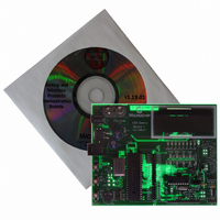
BOARD DEMO FOR MCP215X
Manufacturer
Microchip Technology
Specifications of MCP215XDM
Main Purpose
Interface, IrDA
Embedded
Yes, MCU, 8-Bit
Utilized Ic / Part
MCP2150, MCP2155
Primary Attributes
IrDA Controller with PIC18F MCU
Secondary Attributes
Set up as a Data Logger with LCD, GUI, Socket for EEPROM, Battery Powerable
Processor To Be Evaluated
MCP2150
Silicon Manufacturer
Microchip
Silicon Core Number
MCP2150, MCP2155
Kit Application Type
Interface
Application Sub Type
Standard Protocol Stack Controller
Kit Contents
Board
Rohs Compliant
Yes
Lead Free Status / RoHS Status
Lead free / RoHS Compliant
Lead Free Status / RoHS Status
Lead free / RoHS Compliant, Lead free / RoHS Compliant
Other names
MCP215XDMR
MCP215XDMR
MCP215XDMR
Available stocks
Company
Part Number
Manufacturer
Quantity
Price
Company:

Part Number:
MCP215XDM
Manufacturer:
MICROCHIP
Quantity:
12 000


2.3
FIGURE 2-1:
2004 Microchip Technology Inc.
GETTING STARTED
ICD
VR1
Power
RESET
SW3
SW2
3
Power LED
This section presents an overview of the following system blocks:
• The MCP215X Data Logger Demo Board Hardware
• The MCP215X Data Logger Demo Board Firmware
• The Primary device Graphical User Interface (GUI)
This should give you an understanding of what these components do in the complete
IrDA standard system.
2.3.1
The major components for the MCP215X Data Logger Demo Board are:
1. MCP215X device (U3)
2. Optical transceiver (U5 - TFDS 4500)
3. PICmicro MCU (U1 - PIC16F877)
4. LCD module
5. Power supply
6. User inputs to PICmicro MCU (SW2, SW3 and variable resistor (VR1))
7. PICmicro MCU RESET
8. PICmicro MCU crystal (Y2)
The MCP215X Data Logger Demo Board is fully assembled and tested for evaluation
and demonstration of the MCP2150 or MCP2155 features. A block diagram of the
demo board is shown in Figure 2-1. The board has been designed to allow the instal-
lation of an optional LCD contrast control (VR2) and serial EEPROM device. These
optional components are removed from the MCP215X Data Logger Demo Board block
diagrams for readability.
For more detailed circuit information, refer to Appendix A. “Schematic and Layouts”
and Appendix B. “Bill-Of-Materials (BOM)”.
MCP215X DATA LOGGER DEMO BOARD BLOCK DIAGRAM
Power Supply
The MCP215X Data Logger Demo Board Hardware Overview
9V Battery
J4
PICmicro
(40-pin)
MCU
MCP215X Header
U1
®
Optional
Not
Installed
Optional
Not
Installed
SEE
U2
VR2
JP3
CTS RTS
LCD Module
(2 Line x 16 Character)
Encoder/Decoder
TX
RD7
Installation and Operation
MCP215X
RX
CD
RI
U3
DSR
DTR
JP6
JP5
JP2
JP1
DS51516A-page 11
Discrete
Transceiver
Header 1
J1
J5
RD0
Header 2
U5
JP4
JP7
Related parts for MCP215XDM
Image
Part Number
Description
Manufacturer
Datasheet
Request
R

Part Number:
Description:
Manufacturer:
Microchip Technology Inc.
Datasheet:
Part Number:
Description:
Manufacturer:
Microchip Technology Inc.
Datasheet:
Part Number:
Description:
Manufacturer:
Microchip Technology Inc.
Datasheet:
Part Number:
Description:
Manufacturer:
Microchip Technology Inc.
Datasheet:
Part Number:
Description:
Manufacturer:
Microchip Technology Inc.
Datasheet:
Part Number:
Description:
Manufacturer:
Microchip Technology Inc.
Datasheet:
Part Number:
Description:
Manufacturer:
Microchip Technology Inc.
Datasheet:
Part Number:
Description:
Manufacturer:
Microchip Technology Inc.
Datasheet: