MCP215XDM Microchip Technology, MCP215XDM Datasheet - Page 29
MCP215XDM
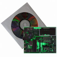
Manufacturer Part Number
MCP215XDM
Description
BOARD DEMO FOR MCP215X
Manufacturer
Microchip Technology
Specifications of MCP215XDM
Main Purpose
Interface, IrDA
Embedded
Yes, MCU, 8-Bit
Utilized Ic / Part
MCP2150, MCP2155
Primary Attributes
IrDA Controller with PIC18F MCU
Secondary Attributes
Set up as a Data Logger with LCD, GUI, Socket for EEPROM, Battery Powerable
Processor To Be Evaluated
MCP2150
Silicon Manufacturer
Microchip
Silicon Core Number
MCP2150, MCP2155
Kit Application Type
Interface
Application Sub Type
Standard Protocol Stack Controller
Kit Contents
Board
Rohs Compliant
Yes
Lead Free Status / RoHS Status
Lead free / RoHS Compliant
Lead Free Status / RoHS Status
Lead free / RoHS Compliant, Lead free / RoHS Compliant
Other names
MCP215XDMR
MCP215XDMR
MCP215XDMR
Available stocks
Company
Part Number
Manufacturer
Quantity
Price
Company:

Part Number:
MCP215XDM
Manufacturer:
MICROCHIP
Quantity:
12 000


TABLE 2-4:
2004 Microchip Technology Inc.
1
2
3
4
5
6
7
8
Step Action
Place both devices on a flat surface about 25 cm (10”)
apart, and with the IR ports facing each other
On the MCP215X Data Logger Demo Board:
Ensure that jumpers JP1 and JP2 are shorted
(closed position).
On the MCP215X Data Logger Demo Board:
Ensure that jumper JP7 is shorted (closed position).
On the MCP215X Data Logger Demo Board:
Insert the 9V battery into the battery holder (BT1) or
plug a 9V AC to DC power supply (such as those
supplied with some Microchip development tools) into
the 9V DC connection plug (J2).
You may need to depress the RESET switch if the
LCD does not display the Microchip program revision
information and then the directions for demo program
selection.
On the MCP215X Data Logger Demo Board:
Depress Switch 2 (SW2).
On the PDA:
Tap on the MCP215XDemo Icon.
On the PDA:
Tap on the Connect button.
On the MCP215X Data Logger Demo Board:
Switch 2 (SW2) increments the soda counter, and
Switch 3 (SW3) increments the candy counter. The
value of the candy and soda counters will be
displayed on the LCD.
Depress Switch 2 until the soda counter displays 7
and depress Switch 3 until the candy counter displays
12.
For demonstration purposes, it is nice when the two
counter values are different.
VENDING MACHINE DEMO - PALM™ PDA
2.4.1.2
After saving the AN888 application program to your PC’s hard drive, the PC can com-
municate with the MCP215X Data Logger Demo Board. Section 2.4.1.2.1 “Steps to
Operate the Vending Machine Demo” discusses how to operate the vending
machine program, while Section 2.4.1.2.2 “Steps to Operate the 250-byte S -> P
Data Transfer Demo” discusses how to operate the 250-byte Secondary device (S) to
Primary device (P) data transfer program.
2.4.1.2.1
The vending machine demo is shown by following the steps in Table 2-4.
RUNNING THE DEMO USING THE APPLICATION NOTE AN888
PROGRAM
Steps to Operate the Vending Machine Demo
Result
—
—
—
On the MCP215X Data Logger Demo Board:
The green power LED (D10) will turn on, the DTR
LED will be on, while all the other UART flow control
signals (CTS, RTS, CD, RI and DSR) will be off. Also,
the RD7 and RD6 LEDs will be on.
On the MCP215X Data Logger Demo Board:
This causes the vending machine program to be
executed.
On the PDA:
The screen will display the MCP215XDemo program
window.
On the PDA:
The Connect button will change to the Disconnect
button.
—
Installation and Operation
DS51516A-page 25
Related parts for MCP215XDM
Image
Part Number
Description
Manufacturer
Datasheet
Request
R

Part Number:
Description:
Manufacturer:
Microchip Technology Inc.
Datasheet:
Part Number:
Description:
Manufacturer:
Microchip Technology Inc.
Datasheet:
Part Number:
Description:
Manufacturer:
Microchip Technology Inc.
Datasheet:
Part Number:
Description:
Manufacturer:
Microchip Technology Inc.
Datasheet:
Part Number:
Description:
Manufacturer:
Microchip Technology Inc.
Datasheet:
Part Number:
Description:
Manufacturer:
Microchip Technology Inc.
Datasheet:
Part Number:
Description:
Manufacturer:
Microchip Technology Inc.
Datasheet:
Part Number:
Description:
Manufacturer:
Microchip Technology Inc.
Datasheet: