ATA6823-DK Atmel, ATA6823-DK Datasheet - Page 11
ATA6823-DK
Manufacturer Part Number
ATA6823-DK
Description
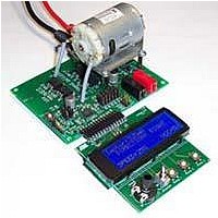
BOARD EVALUATION FOR ATA6823
Manufacturer
Atmel
Type
PWM Controllersr
Specifications of ATA6823-DK
Main Purpose
Power Management, Motor Control
Embedded
No
Utilized Ic / Part
ATA6823
Primary Attributes
Brush DC Motors, 8 ~ 18V, LIN Interface, Watchdog, 5V Regulator
Secondary Attributes
Cross Conduction, Under/Over Voltage, Short Circuit, & Temperature Protection
Input Voltage
8 V to 18 V
Product
Power Management Modules
Lead Free Status / RoHS Status
Contains lead / RoHS non-compliant
For Use With/related Products
ATA6823


3.5
3.6
3.7
4961B–AUTO–02/11
Motor Bridge OFF
Inrush Current
Output Short Circuit
The intent is to monitor a dedicated H-bridge power supply.
An overvoltage or undervoltage condition at pin VBAT will be indicated by a high level at the
diagnostic pin DG2. To debounce, a 13-kHz low-pass filter is inserted.
Charge pump voltage lower than V
debouncing time of 30µs.
If overtemperature of higher than 150°C is detected, the pin DG3 is set to high. The occur-
rence of overtemperature will be latched until the next watchdog pulse.
If monitoring signals DG2 or DG3 indicate failure, the ATA6823 will switch off the motor bridge.
When the PWM signal is set to low, both high-side MOSFETs are switched on to slow the
motor down. Cruise Control guarantees fly back currents over the contrary highside
N-MOSFET.
Switching a motor load on immediately to 100% duty cycle causes a voltage drop due to the
inrush current. This drop depends on the power supply installation. Depending on the level of
voltage drop, the Atmel
proper connection between the power supply and application board is essential.
Use the PWM feature when supplying powerful motors and limiting their starting current.
Five different short circuit conditions need to be considered. In the following comments, a
static motor clamp will be the clamp which is switched to VBAT. This high-side switch is not
PWM controlled, it is permanently on. Dynamic motor clamp will be the low-side clamp switch
to GND, which is controlled by PWM.
1. Short between both motor clamps
2. Short between static motor clamp and ground
In an ideal short circuit, 2 output switches and 1 inverse polarity protection switch are in
serial. In this case, R
by pin S1 or S2: One of the two drain source voltage drops of the output FETs is higher
than 4V and will switch DG1 on.
If the supply voltage is lower than 12V or the short circuit is not ideal (that is, the drain
source voltage drop over both output switches is lower than 4V each) the reservoir capac-
itor will be discharged. Voltage monitoring at PBAT will set DG1. The PBAT voltage
monitoring also will detect failure if PWM duty cycle time is shorter than 10µs, because
10µs is the delay time until short circuit detection.
For an ideal short circuit and supply voltage higher than 8V, minimum one of the output
drops is higher than 4V. The sense pin S1 or S2 will switch the pin DG1.
In all other cases, PBAT monitoring will switch DG1, if PBAT falls below 5.6V.
®
dsON
ATA6823 detects short circuits as described below. A short and
and supply voltage higher than 12V short circuit will be detected
VBAT
+ 4V will be indicated by DG2 set to high, with a
Atmel ATA6823
11
Related parts for ATA6823-DK
Image
Part Number
Description
Manufacturer
Datasheet
Request
R

Part Number:
Description:
IC H-BRIDGE MOTOR DRIVER 32-QFN
Manufacturer:
Atmel
Datasheet:

Part Number:
Description:
Motor / Motion / Ignition Controllers & Drivers Gate Driver IC
Manufacturer:
Atmel
Datasheet:

Part Number:
Description:
H-bridge Motor Driver
Manufacturer:
ATMEL Corporation
Datasheet:

Part Number:
Description:
DEV KIT FOR AVR/AVR32
Manufacturer:
Atmel
Datasheet:
Part Number:
Description:
INTERVAL AND WIPE/WASH WIPER CONTROL IC WITH DELAY
Manufacturer:
ATMEL Corporation
Datasheet:
Part Number:
Description:
Low-Voltage Voice-Switched IC for Hands-Free Operation
Manufacturer:
ATMEL Corporation
Datasheet:
Part Number:
Description:
MONOLITHIC INTEGRATED FEATUREPHONE CIRCUIT
Manufacturer:
ATMEL Corporation
Datasheet:
Part Number:
Description:
AM-FM Receiver IC U4255BM-M
Manufacturer:
ATMEL Corporation
Datasheet:
Part Number:
Description:
Monolithic Integrated Feature Phone Circuit
Manufacturer:
ATMEL Corporation
Datasheet:
Part Number:
Description:
Multistandard Video-IF and Quasi Parallel Sound Processing
Manufacturer:
ATMEL Corporation
Datasheet:
Part Number:
Description:
High-performance EE PLD
Manufacturer:
ATMEL Corporation
Datasheet:
Part Number:
Description:
8-bit Flash Microcontroller
Manufacturer:
ATMEL Corporation
Datasheet: