MCP3909RD-3PH1 Microchip Technology, MCP3909RD-3PH1 Datasheet - Page 30
MCP3909RD-3PH1
Manufacturer Part Number
MCP3909RD-3PH1
Description
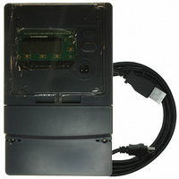
REF DESIGN MCP3909 3PH ENGY MTR
Manufacturer
Microchip Technology
Datasheets
1.MCP3909T-ISS.pdf
(44 pages)
2.MCP3909T-ISS.pdf
(104 pages)
3.MCP3909RD-3PH3.pdf
(88 pages)
Specifications of MCP3909RD-3PH1
Main Purpose
Power Management, Energy/Power Meter
Embedded
No
Utilized Ic / Part
MCP3909, PIC18F2520, PIC18F4550
Primary Attributes
3-Ph, 220 VAC, In Case, LCD, USB, GUI
Secondary Attributes
Opto-Isolated Interface for Safety
Operating Voltage
220 V
Operating Current
5 A
Description/function
Energy Meter
For Use With/related Products
MCP3909
Lead Free Status / RoHS Status
Not applicable / Not applicable


MCP3909
5.7
With microcontroller SPI ports, it is required to send
groups of eight bits. It is also required that the
microcontroller SPI port be configured to clock out data
on the falling edge of clock and latch data in on the
rising edge, or vice versa depending on the mode.
TABLE 5-4:
DS22025B-page 30
Standard SPI
Terminology
Mode
0,0
0,1
1,0
1,1
Using the MCP3909 with
Microcontroller (MCU) SPI Ports
SPI MODE COMPATIBILITY
PIC Control Bits
CKP
0
0
1
1
State
CKE
1
0
1
0
Compatibility
MCP3909
—
—
—
√
Idle state for clock is low level, transmit (from PIC)
occurs from active to idle clock state
Idle state for clock is low level, transmit (from PIC)
occurs from idle to active clock state
Idle state for clock is high level, transmit (from PIC)
occurs from active to idle clock state
Idle state for clock is high level, transmit (from PIC)
occurs from idle to active clock state
5.7.1
The following table represents the standard SPI mode
terminology, the respective PIC bit settings, and a
description of compatibility for the MCP3909 device.
The MCP3909 works in SPI mode 0,1 mode, that is the
data is clocked out of the part on the rising edge and
clocked in on the falling edge of SCK.
SPI MODE DEFINITIONS
Description
© 2009 Microchip Technology Inc.
Related parts for MCP3909RD-3PH1
Image
Part Number
Description
Manufacturer
Datasheet
Request
R

Part Number:
Description:
BOARD DES MCP3909 ENERGY METER
Manufacturer:
Microchip Technology
Datasheet:

Part Number:
Description:
REF DESIGN FOR MCP3909 W/18F2520
Manufacturer:
Microchip Technology
Datasheet:

Part Number:
Description:
Manufacturer:
Microchip Technology Inc.
Datasheet:
Part Number:
Description:
Manufacturer:
Microchip Technology Inc.
Datasheet:
Part Number:
Description:
Manufacturer:
Microchip Technology Inc.
Datasheet:
Part Number:
Description:
Manufacturer:
Microchip Technology Inc.
Datasheet:
Part Number:
Description:
Manufacturer:
Microchip Technology Inc.
Datasheet:
Part Number:
Description:
Manufacturer:
Microchip Technology Inc.
Datasheet:
Part Number:
Description:
Manufacturer:
Microchip Technology Inc.
Datasheet:
Part Number:
Description:
Manufacturer:
Microchip Technology Inc.
Datasheet: