AT89STK-09 Atmel, AT89STK-09 Datasheet
AT89STK-09
Specifications of AT89STK-09


Related parts for AT89STK-09


AT89STK-09 Summary of contents
Page 1
... AT89STK-09 Starter Kit for AT83C26 .............................................................................................. User Guide ...
Page 2
... AT89STK-09 User Guide Section 1 Introduction ........................................................................................... 1-2 1.1 Acronyms ..................................................................................................1-2 1.2 Features ....................................................................................................1-2 Section 2 Hardware .............................................................................................. 2-6 2.1 Power Supply ............................................................................................2-6 2.2 Jumper Configuration................................................................................2-6 2.3 Host Microcontroller Connection ...............................................................2-6 2.4 Test points ................................................................................................2-9 Section 3 Quick Start .......................................................................................... 3-12 3.1 Smart cards Insertion ..............................................................................3-12 3 ...
Page 3
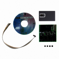
... TWI : Inter Integrated Circuit • SCIB: Smart Card Interface Bus • LDO : Low Drop Output (Regulator) The AT89STK-09 Board provides the following features: • AT89STK09 board with 2 ISO7816-3 connectors and 4 SIM/SAM connectors • 2 Gemplus GemClub Smart cards • One 20 multicolor wires cable with HE10 connector • ...
Page 4
... TWI master signals from a host microcontroller board SCIB signals connected to AT89STK09 board Smart card clock from host microcontroller board Figure 1-2. Configuration Description Host Microcontroller board Internal Pull ups SCIB signals TWI master Connection with wires AT89STK09 board Smart Card AT89STK-09 User Guide Power Supply DC 5V ...
Page 5
... Host Microcontroller Connection AT89STK-09 User Guide The AT89STK09 requires power supply, clock signal , smart card and TWI commands to run. U1 connector is used to connect the AT83C26 host pins to the host microcontrol- ler. The U1 connector pins are described on Table 2-1. All passive components needed (inductors, capacitors) are soldered on board. ...
Page 6
... R1, R2 recommended values are between 27KOhms to 1MOhms. By default, resistors value is 180KOhms #1 Name Color 11 AUX1 Brown 12 Not Connected Red 13 IO2 Orange 14 BY PASS Yellow 15 IO1 Green 16 VSS Blue 17 SCL Velvet 18 VCC Grey 19 SDA Blank 20 EVCC Black AT89STK-09 User Guide ...
Page 7
... Figure 2-1. AT89STK09 board J2 J1 J3, J4, J5, J6 AT89STK-09 User Guide J2 Hardware 2-6 7521B–SCR–10/05 ...
Page 8
... Hardware 2.4 Test Points CVCC2 2-7 7521B–SCR–10/05 CVCC3 Caution : Active probe use is recommended to measure all smart card interfaces signals SIgnal DC/DCB CVCC1 CVCC5 CVCC4 AT89STK-09 User Guide ...
Page 9
... Smart cards Insertion AT89STK-09 User Guide Be carreful with the direction of the smart cards in the connector. Figure 3-1. Smart Card Direction J2 Section 3 Quick Start 3-8 7521B–SCR–10/05 ...
Page 10
... Component Side 3-9 7521B–SCR–10/05 The board layout has been optimized in order to reduce the noise, overshoot & under- shoot on the smart card interface signals. The board is used to pass EMV certification level 1. Gerber file is available on demand at cardreader@atmel.com Solder Side AT89STK-09 User Guide ...
Page 11
... AT89STK-09 User Guide Schematics & Bill Of Material Schematics & Bill Of Material Section 4 4-10 7521B–SCR–10/05 ...
Page 12
... Schematics & Bill Of Material 4-11 7521B–SCR–10/05 AT89STK-09 User Guide ...
Page 13
... AT89STK-09 User Guide Schematics & Bill Of Material 4-12 7521B–SCR–10/05 ...
Page 14
... Schematics & Bill Of Material 4-13 7521B–SCR–10/05 AT89STK-09 User Guide ...
Page 15
... Bill Of Material AT89STK-09 User Guide Reference Part C1,C2,C3,C4,C5,C6 C7, C8, C9, C10, C22, C23, C24, C25, C26, C27 C11,C13, C15 100 nF C14 10µF C20,C21 2.2 µF C17,C18,C19 470 nF C16 4.7 µF C12 10 µF R1,R2 180 KOhms L1,L2 10 µH U2 AT83C26 Schematics & Bill Of Material ...
Page 16
... No licenses to patents or other intellectual property of Atmel are granted by the Company in connection with the sale of Atmel products, expressly or by implication. Atmel’s products are not authorized for use as critical components in life support devices or systems. ...