AT89STK-11 Atmel, AT89STK-11 Datasheet
AT89STK-11
Specifications of AT89STK-11


Related parts for AT89STK-11


AT89STK-11 Summary of contents
Page 1
... AT89STK-11 Starter Kit .............................................................................................. Hardware User Guide ...
Page 2
... AT89STK-11 Hardware User Guide Section 1 Introduction ........................................................................................... 1-1 1.1 Features ....................................................................................................1-1 1.2 Supported Devices....................................................................................1-2 Section 2 Hardware Description ........................................................................... 2-4 2.1 Board Overview.........................................................................................2-4 2.2 Block Diagram...........................................................................................2-5 2.3 Power Supply ............................................................................................2-5 2.4 Reset.........................................................................................................2-6 2.5 Features ....................................................................................................2-7 2.6 Interfaces ..................................................................................................2-7 2.7 Board Settings ..........................................................................................2-9 Section 3 ISP Programming ...
Page 3
... Features AT89STK-11 Hardware User Guide This document describes the AT89STK-11 board dedicated to the standard C51 micro- controllers with in-system programming. All of the microcontroller I/Os are made available in an expansion area with prototyping facilities. Stand-alone Board In-System Programmable (ISP) including ‘Auto ISP’ feature ...
Page 4
... Supported Devices AT89STK-11 Hardware User Guide AT89C51RE2 AT89C51RB2 AT89C51RC2/IC2 AT89C51RD2/ID2/ED2 Introduction 1-2 7676B–8051–08/07 ...
Page 5
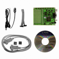
... Board Overview AT89STK-11 Hardware User Guide Figure 2-1 shows the AT89STK-11 board. Figure 2-1. AT89STK-11 This photo is not contractual and may be modified without notification by Atmel. Section 2 Hardware Description 2-4 7676B–8051–08/07 ...
Page 6
... Power Supply 2.3.1 Power Supply Sources 2.3.1.1 JACK PWR Connector 2-5 7676B–8051–08/07 Figure 2-2 shows the functional block diagram of the AT89STK-11, with the I/O usage. PC Host Full UART C51 PLCC44 Leds: PWR User LEDs ALE The on-board power supply circuitry allows various power supply configurations. This gives the user the capability to power the devices in the 3V and in the 5V voltage range ...
Page 7
... AT89STK-11 Hardware User Guide Figure 2-3. Male JACK Outlet and Wires Note: Do not mount more than one power supply source on AT89STK-11 Board. Note: There is a diode voltage level between the negative output of the power supply and the “GND”. This could introduce some voltage gap during measurement and instrumentation ...
Page 8
... The signals sda and scl are controlled by the TWI ports of MCU. This TWI bus is also connected to the expansion area. External TWI pull-ups are not provided on the AT89STK-11. The SPI connector is directly connected to SPI I/O of the MCU. The DB9 connector is connected to on-chip UART peripheral through a standard RS232 driver/receiver ...
Page 9
... Jumpers 2.7.2 Solder Straps AT89STK-11 Hardware User Guide This interface enables the debug of the application through ATMEL OCD dongle for AT89C51RE2/IE2/RD3/IE3 only. In addition to a 16x29 pad array, two rows of pads are given on the right side of the board to offer all the MCU signals tu user application. Any application expansion can be built on board through this interface ...
Page 10
... Figure 2-6. Solder Strap Definition Test points are used to check the internal power supply of the microcontroller. Table 2-3. Table of Test Points Reference PCB Label TP1 VCC TP2,TP3 GND Function Test point for Vcc Test point for GND AT89STK-11 Hardware User Guide ...
Page 11
... Auto ISP Mode 3.2.1 Board Configuration AT89STK-11 Hardware User Guide The On-Chip memories and configuration bytes can be programmed using the ISP mode of the device and Atmel's FLexible In-system Programmer Software (FLIP) described below. See Section “FLIP Software”, page 11. ...
Page 12
... Autoisp function is an operation which allows to enter in ISP mode without any hardware handling.This is done thanks to DTR and RTS RS232 signals which can control on the Board the RST and PSEN I/O of MCU. ® and Linux Operating Systems. FLIP supports in-sys- ® 2 one : you can compile and link your AT89STK-11 Hardware User Guide ...
Page 13
... Figure 4-1. Board Components View Diagram AT89STK-11 Hardware User Guide Appendix A: Board Layout Section 4 4-12 7676B–8051–08/07 ...
Page 14
... R24 R4,R6,R8,R9,R10,R11,R12, R13 SP1,SP2,SP3,SP4,SP5, SP6 SP7, SP8, SP9, SP10, SP11, SP12 20 8 SW1,SW2,SW3,SW4,SW5,SW6, SW7,SW8 AT89STK-11 Hardware User Guide Appendix B: Bill of Materials Part Tech. Caracteristics 100n 50V-10% Ceramic 1µF 10Vmin ±10% 22pF 10Vmin ±10% Red Led I=10 mA Green Led I=10 mA SIP2 SOCKET ...
Page 15
... 25bis U7, 28bis 2 Y1 R100, R101, R102, R103 R104, R105, R106, R107 AT89STK-11 Hardware User Guide Part Tech. Caracteristics TEST POINT Through Hole Pad DF005S LM317 AT8xC51_PLCC44 Socket AT8xC51_PLCC44 SIPEX-SP3232ECA Ref=SP3232ECA 74HC125/SO CRYSTAL HC49 CRYSTAL tulip 4,7K 0.06W, 5% Appendix B: Bill of Materials Package Manufacturer Hole 1 ...
Page 16
... AT89STK-11 Hardware User Guide Appendix C: Board Schematics 4-15 7676B–8051–08/07 ...
Page 17
... Figure 4-2. AT89STK-11 Schematics ( AT89STK-11 Hardware User Guide 1 ADJ 1 2 Appendix C: Board Schematics 4-16 7676B–8051–08/07 ...
Page 18
... Appendix C: Board Schematics Figure 4-3. AT89STK-11 Schematics ( 4-17 7676B–8051–08/07 LED_7 LED_6 LED_5 LED_4 LED_3 LED_2 LED_1 LED_0 AT89STK-11 Hardware User Guide ...
Page 19
... Figure 4-4. AT89STK-11 Schematics ( VCC 44 AT89STK-11 Hardware User Guide Appendix C: Board Schematics Tx_OCD 23 GND 22 4-18 7676B–8051–08/07 ...
Page 20
... Appendix C: Board Schematics Figure 4-5. AT89STK-11 Schematics ( VCC 16 4-19 7676B–8051–08/ GND 15 VCC 16 GND AT89STK-11 Hardware User Guide ...
Page 21
... References 4.3 Acronyms AT89STK-11 Hardware User Guide Appendix D: References/Acronyms AT89C51RD2/ID2/ED2/RB2/RC2/IC2/RE2/IE2 and AT89C51RD3/IE3 Product Datasheet. FLIP: FLexible In-system Programming ISP: In-System programming 4-20 7676B–8051–08/07 ...
Page 22
... Section 3.1.1, page 3-11 : SW1 switch and EA jumper do not exist. 4. Appendix A, page 4-13 : the given board layout was wrong. Replaced by the right one. 5. Appendix C, page 4-19 : there was an error on page 4 of the schematic. Pin5 of U9B is now connected to Vcc instead of GND. AT89STK-11 Hardware User Guide ...
Page 23
... Atmel does not make any commitment to update the information contained herein. Unless specifically providedot- herwise, Atmel products are not suitable for, and shall not be used in, automotive applications. Atmel’sAtmel’s products are not intended, authorized, or warranted for use as components in applications intended to support or sustain life. © ...