OM6281 NXP Semiconductors, OM6281 Datasheet
OM6281
Specifications of OM6281
Available stocks


Related parts for OM6281


OM6281 Summary of contents
Page 1
... Content Keywords I2C, PCA9698, GPIO Abstract The OM6281 is an add-on to NXP’s I daughter board makes it easy to test and design with the PCA9698, a Fast-mode Plus (Fm+) 40-bit GPIO device. These boards, along with the I2CUSB Lite GUI (PC based), provide an easy to use evaluation platform. ...
Page 2
... Date Description 01 20080924 Initial release Contact information For more information, please visit: For sales office addresses, please send an email to: UM10267_1 User manual http://www.nxp.com salesaddresses@nxp.com Rev. 01 — 24 September 2008 UM10267 PCA9698 demonstration board OM6281 © NXP B.V. 2008. All rights reserved ...
Page 3
... PC USB port. Care should be taken not to exceed the USB port current capabilities. UM10267_1 User manual PCA9698 demonstration board OM6281 2 C-bus is helpful but not required Demonstration Board 2005-1 and OM6281 hardware Rev. 01 — 24 September 2008 UM10267 2 C-bus 2 C-bus/SMBus port. The © NXP B.V. 2008. All rights reserved. ...
Page 4
... OM6281 connection The I C 2005-1 board should be disconnected from your PC. The OM6281 board has a 9-pin female connector that allows the demo board to mount directly onto the I board at the JP1 location. Connect the OM6281 board to the I Once the board is connected, connect the USB cable and start the WIN-I2CUSB Lite software ...
Page 5
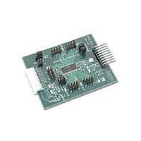
... Hardware description address select 9-pin connector to I2C 2005-1 board Fig 1. OM6281 demo board The OM6281 board has 8 jumper headers. • Port0: Headers for port 0 I/O bits 0.0 through 0.7 • Port1: Headers for port 1 I/O bits 1.0 through 1.7 • Port2: Headers for port 2 I/O bits 2.0 through 2.7 • ...
Page 6
... RESET PIN56 RESET INT PIN55 INT OE PIN30 unswitched PIN29 AD2 PIN28 AD1 PIN27 AD0 AD1 GND Fig 2. OM6281 schematic (part unswitched IO0.4 IO0.5 IO0.6 IO0.7 PIN13 IO1.0 PIN14 IO1.1 PIN15 IO1.2 PIN16 IO1.3 PIN17 IO1.4 PIN19 IO1.5 PIN20 IO1.6 PIN21 IO1.7 ...
Page 7
... RESET LED1 PIN1 A0 GND US7 5 V unswitched 5 V switched 3.3 V unswitched 3.3 V switched SCL GND SDA INPUT OUTPUT training board header Fig 3. OM6281 schematic (part GND IC3 PIN2 LED0 PS1 A PIN3 LED1 PS2 B GND US2 5 V unswitched 5 V switched 3.3 V unswitched 3 ...
Page 8
... NXP Semiconductors 7. OM6281 demonstration board main components Table 1. Device PCA9698DGG PCA9530DP 74LVC1G38 8. PCA9698 evaluation steps The PCA9698 functions are controlled by WIN-I2CUSB Lite GUI. Refer to the PCA9698 data sheet for additional information on the registers and functionality. 8.1 Controlling LEDs using GPIO output 1 ...
Page 9
... NXP Semiconductors Fig 4. PCA9698 device configuration screen Fig 5. Bank0 configuration UM10267_1 User manual PCA9698 demonstration board OM6281 Rev. 01 — 24 September 2008 UM10267 © NXP B.V. 2008. All rights reserved ...
Page 10
... PCA9530. A 74LVC1G38GW NAND gate is used to demonstrate the OE polarity inversion (active HIGH instead of default active LOW) of the PCA9698. UM10267_1 User manual PCA9698 demonstration board OM6281 Section 8.2.2 may be a more efficient method of verifying changes of Rev. 01 — 24 September 2008 UM10267 © ...
Page 11
... User manual LED control truth table LED1 will demonstrate how to obtain the waveform shown in Rev. 01 — 24 September 2008 UM10267 PCA9698 demonstration board OM6281 Table 2 illustrates the sequence. GPIO output LED LOW ON LOW ON LOW ON LOW OFF Figure 6. © NXP B.V. 2008. All rights reserved. ...
Page 12
... Verify the blink color is now blue. 24. Slide the Period and Duty Cycle bars for the LED1 and LED0 and observe how the blink and dim patterns vary. UM10267_1 User manual PCA9698 demonstration board OM6281 Rev. 01 — 24 September 2008 UM10267 Section 4 “Installation”. ...
Page 13
... General Purpose Input/Output Graphical User Interface Input/Output Inter Integrated Circuit bus Integrated Circuit Light-Emitting Diode Personal Computer Random Access Memory Red/Green/Blue System Management Bus Universal Serial Bus Rev. 01 — 24 September 2008 UM10267 PCA9698 demonstration board OM6281 © NXP B.V. 2008. All rights reserved ...
Page 14
... PCA9698 data sheet — NXP Semiconductors [2] PCA9530 data sheet — NXP Semiconductors [3] 74LVC1G38 data sheet — NXP Semiconductors 2 [ 2005-1 User Manual — NXP Semiconductors UM10267_1 User manual PCA9698 demonstration board OM6281 Rev. 01 — 24 September 2008 UM10267 © NXP B.V. 2008. All rights reserved ...
Page 15
... This document supersedes and replaces all information supplied prior to the publication hereof. UM10267_1 User manual PCA9698 demonstration board OM6281 Suitability for use — NXP Semiconductors products are not designed, authorized or warranted to be suitable for use in medical, military, aircraft, space or life support equipment, nor in applications where failure or ...
Page 16
... Minimum system requirements 3.4 Power requirements . . . . . . . . . . . . . . . . . . . . . 3 4 Installation . . . . . . . . . . . . . . . . . . . . . . . . . . . . . 2005-1 board and WIN-12CUSB Lite software . . . . . . . . . . . . . . . . . . . . . . . . . . . . . . 4 2 4.2 OM6281 connection 2005-1 board . . . . . 4 5 Hardware description . . . . . . . . . . . . . . . . . . . . 5 6 Schematics . . . . . . . . . . . . . . . . . . . . . . . . . . . . . 6 7 OM6281 demonstration board main components . . . . . . . . . . . . . . . . . . . . . . . 8 8 PCA9698 evaluation steps . . . . . . . . . . . . . . . . 8 8.1 Controlling LEDs using GPIO output . . . . . . . . 8 8 ...