AD5171EVAL Analog Devices Inc, AD5171EVAL Datasheet - Page 5
AD5171EVAL
Manufacturer Part Number
AD5171EVAL
Description
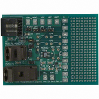
BOARD EVAL FOR AD5171
Manufacturer
Analog Devices Inc
Datasheet
1.AD5171BRJZ10-R7.pdf
(24 pages)
Specifications of AD5171EVAL
Main Purpose
Digital Potentiometer
Utilized Ic / Part
AD5171
Lead Free Status / RoHS Status
Contains lead / RoHS non-compliant
Secondary Attributes
-
Embedded
-
Primary Attributes
-


TIMING CHARACTERISTICS: 5 kΩ, 10 kΩ, 50 kΩ, AND 100 kΩ
V
Table 2.
Parameter
INTERFACE TIMING CHARACTERISTICS (APPLY TO ALL PARTS
1
2
3
Typical specifications represent average readings at 25°C and V
Guaranteed by design; not subject to production test.
All dynamic characteristics use V
DD
SCL Clock Frequency
t
t
t
t
t
t
t
t
t
t
OTP Program Time
BUF
HD;STA
LOW
HIGH
SU;STA
HD;DAT
SU;DAT
F
R
SU;STO
= 3 V to 5 V ± 10%, V
Fall Time of Both SDA and SCL Signals
Rise Time of Both SDA and SCL Signals
Bus Free Time Between Start and Stop
Low Period of SCL Clock
High Period of SCL Clock
Setup Time for Start Condition
Hold Time (Repeated Start)
Data Setup Time
Setup Time for Stop Condition
Data Hold Time
SDA
SCL
A
DD
= V
= 5 V.
P
DD
t
, V
1
B
S
= 0 V, −40°C < T
t
2
t
8
t
3
t
8
DD
Figure 3. Interface Timing Diagram
= 5 V.
A
< +125°C, unless otherwise noted.
t
9
2, 3
Rev. D | Page 5 of 24
)
t
4
Symbol
f
t
t
t
t
t
t
t
t
t
t
t
t
SCL
1
2
3
4
5
6
7
8
9
10
11
9
t
5
Conditions
After this period, the
first clock pulse is generated
t
6
t
7
P
Min
1.3
0.6
1.3
0.6
0.6
0.1
0.6
t
10
Typ
400
1
Max
400
50
0.9
0.3
0.3
AD5171
Unit
kHz
μs
μs
μs
μs
μs
μs
μs
μs
μs
μs
ms
Related parts for AD5171EVAL
Image
Part Number
Description
Manufacturer
Datasheet
Request
R


Part Number:
Description:
Board Mount Temperature Sensors TEMP MONITR DUAL CHN W/SERIES RSTNCE CNCL
Manufacturer:
ON Semiconductor
Datasheet:

Part Number:
Description:
Touch Screen Digitizer
Manufacturer:
Analog Devices, Inc.
Datasheet:
Part Number:
Description:
Half-duplex Icoupler-r Isolated Rs-485 Transceiver
Manufacturer:
Analog Devices, Inc.
Datasheet:

Part Number:
Description:
±1.7g Dual-Axis IMEMS Accelerometer Evaluation Board
Manufacturer:
Analog Devices Inc
Datasheet:

Part Number:
Description:
Inertial Sensor Evaluation System
Manufacturer:
Analog Devices Inc
Datasheet:
Part Number:
Description:
Manufacturer:
Analog Devices Inc
Datasheet:
Part Number:
Description:
Manufacturer:
Analog Devices Inc
Datasheet:
Part Number:
Description:
Manufacturer:
Analog Devices Inc
Datasheet:
Part Number:
Description:
Manufacturer:
Analog Devices Inc
Datasheet:
Part Number:
Description:
Manufacturer:
Analog Devices Inc
Datasheet: