RDK-128 Power Integrations, RDK-128 Datasheet - Page 16
RDK-128
Manufacturer Part Number
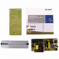
RDK-128
Description
KIT REF DESIGN 36-72W MOTOR DRVR
Manufacturer
Power Integrations
Specifications of RDK-128
Main Purpose
Power Management, Motor Control
Embedded
No
Utilized Ic / Part
PKS606
Primary Attributes
Variable Speed 12V 36W DC Motor, 90 ~ 265 VAC
Secondary Attributes
External Potentiometer or Variable DC Voltage Speed Control
Lead Free Status / RoHS Status
Not applicable / Not applicable
Other names
596-1198


RDR-128 36 W, 72 W Peak Variable Output Power Supply
AE
LE
AL
BW
M
L
NS
DC INPUT VOLTAGE PARAMETERS
VMIN
VMAX
CURRENT WAVEFORM SHAPE PARAMETERS
DMAX
IAVG
IP
IR
IRMS
TRANSFORMER PRIMARY DESIGN PARAMETERS
LP
LP_TOLERANCE
NP
ALG
Target BM
BM
BAC
ur
LG
BWE
OD
INS
DIA
AWG
CM
CMA
TRANSFORMER SECONDARY DESIGN PARAMETERS
Lumped parameters
ISP
ISRMS
IRIPPLE
CMS
AWGS
VOLTAGE STRESS PARAMETERS
VDRAIN
PIVS
Power Integrations, Inc.
Tel: +1 408 414 9200 Fax: +1 408 414 9201
www.powerint.com
2.00
4
0.404
10.20
24.57
13.82
12.45
1420
3000
2910
2053
2763
7.34
0.00
0.61
1.37
2.60
1.21
1.82
0.45
20.4
0.54
0.07
0.47
375
148
104
677
323
177
665
87
12
38
25
15
52
2
4
Amps
Amps
Amps
uHenrie
Cmils/A
Cmils
AWG
nH/T^2
nH/T^2
Volts
Volts
Gauss
Gauss
Gauss
Amps
Amps
Amps
Amps
Cmils
cm^2
AWG
Volts
Volts
mm
mm
mm
mm
mm
mm
mm
cm
mp
%
s
Peak Secondary Current
Secondary RMS Current
Output Capacitor RMS Ripple Current
Secondary Bare Conductor minimum circular mils
Secondary Wire Gauge (Rounded up to next larger
standard AWG value)
Maximum Drain Voltage Estimate (Assumes 20%
zener clamp tolerance and an additional 10%
temperature tolerance)
Output Rectifier Maximum Peak Inverse Voltage
Core Effective Cross Sectional Area
Core Effective Path Length
Ungapped Core Effective Inductance
Bobbin Physical Winding Width
Safety Margin Width (Half the Primary to
Secondary Creepage Distance)
Number of Primary Layers
Number of Secondary Turns
Minimum DC Input Voltage
Maximum DC Input Voltage
Duty Ratio at full load, minimum primary
inductance and minimum input voltage
Average Primary Current
Minimum Peak Primary Current
Primary Ripple Current
Primary RMS Current
Typical Primary Inductance. +/- 12% to ensure a
minimum primary inductance of 132 uH
Primary inductance tolerance
Primary Winding Number of Turns
Gapped Core Effective Inductance
Target Peak Flux Density at Maximum Current
Limit
Calculated Maximum Operating Flux Density, BM <
3000 is recommended
AC Flux Density for Core Loss Curves (0.5 X Peak
to Peak)
Relative Permeability of Ungapped Core
Gap Length (Lg > 0.1 mm)
Effective Bobbin Width
Maximum Primary Wire Diameter including
insulation
Estimated Total Insulation Thickness (= 2 * film
thickness)
Bare conductor diameter
Primary Wire Gauge (Rounded to next smaller
standard AWG value)
Bare conductor effective area in circular mils
Primary Winding Current Capacity (100 < CMA <
500)
Page 16 of 32
16-Aug-07
Related parts for RDK-128
Image
Part Number
Description
Manufacturer
Datasheet
Request
R

Part Number:
Description:
KIT REF DESIGN FOR LNK457D
Manufacturer:
Power Integrations
Datasheet:

Part Number:
Description:
REFERENCE DESIGN LINKSWITCH-PH
Manufacturer:
Power Integrations
Datasheet:

Part Number:
Description:
KIT REF DESIGN FOR LNK403EG
Manufacturer:
Power Integrations
Datasheet:

Part Number:
Description:
KIT REF DESIGN FOR LNK406EG
Manufacturer:
Power Integrations
Datasheet:

Part Number:
Description:
KIT REF DESIGN LINKSWITCH-CV
Manufacturer:
Power Integrations
Datasheet:

Part Number:
Description:
KIT REF DESIGN LINKSWITCH 2
Manufacturer:
Power Integrations
Datasheet:

Part Number:
Description:
Specifications: Family: Eval Boards - DC/DC & AC/DC (Off-Line) SMPS ; Series: HiperLCS™ ; Main Purpose: DC/DC, Step Down ; Outputs and Type: 1, Isolated ; Power - Output: 150W ; Voltage - Output: 24V ; Current - Output: 6.25A ; Voltage - Input:
Manufacturer:
Power Integrations, Inc.
Datasheet:

Part Number:
Description:
KIT DESIGN REF TINYSWITCH-III
Manufacturer:
Power Integrations
Datasheet:

Part Number:
Description:
KIT DESIGN REF LINKSWITCH LP
Manufacturer:
Power Integrations
Datasheet:

Part Number:
Description:
KIT REF DESIGN LED LINKSWITCH TN
Manufacturer:
Power Integrations
Datasheet:
Part Number:
Description:
KIT REF DESIGN FOR LNK457D
Manufacturer:
Power Integrations
Datasheet:
Part Number:
Description:
REFERENCE DESIGN LINKSWITCH-PH
Manufacturer:
Power Integrations
Datasheet:
Part Number:
Description:
Specifications: Manufacturer: Power Integrations ; Output Voltage: 380 VDC ; Input / Supply Voltage (Max): 264 VAC ; Input / Supply Voltage (Min): 90 VAC ; Mounting Style: Through Hole ; Output Current: 0.913 A ; Output Power: 347 W
Manufacturer:
Power Integrations, Inc.
Part Number:
Description:
Specifications: Family: Eval Boards - DC/DC & AC/DC (Off-Line) SMPS ; Series: HiperLCS™ ; Main Purpose: DC/DC, Step Down ; Outputs and Type: 1, Isolated ; Power - Output: 150W ; Voltage - Output: 24V ; Current - Output: 6.25A ; Voltage - Input:
Manufacturer:
Power Integrations, Inc.
Datasheet: