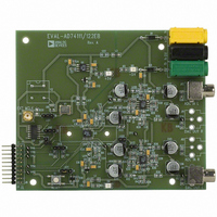
EVAL-AD74111EBZ Analog Devices Inc, EVAL-AD74111EBZ Datasheet - Page 3

EVAL-AD74111EBZ
Manufacturer Part Number
EVAL-AD74111EBZ
Description
BOARD EVAL FOR AD74111
Manufacturer
Analog Devices Inc
Specifications of EVAL-AD74111EBZ
Main Purpose
Interface, Analog Front End (AFE)
Utilized Ic / Part
AD74111
Lead Free Status / RoHS Status
Lead free / RoHS Compliant
Secondary Attributes
-
Embedded
-
Primary Attributes
-
Lead Free Status / Rohs Status
Supplier Unconfirmed
EVALUATION BOARD HARDWARE
OPERATING THE AD741111 EVALUATION BOARD
Power Supplies
The evaluation board requires a supply of +5 V, GND, and −5 V.
Voltage regulators on the evaluation board regulate these
supplies to produce an analog and digital 2.5 V and digital 3 V
for the codec. The ±5 V supplies are used to power the op amps.
All the supplies are decoupled with 10 μF tantalum and 0.1 μF
ceramic capacitors.
Extensive ground planes are used on this board to minimize the
effect of high frequency noise interference. There are two
ground planes, AGND and DGND. These are connected at one
location close to the AD74111.
The AD74111 evaluation board uses shorted links to allow
additional testing, such as current measurement or the use of
separate supplies. The links are not populated on the boards,
and if it is required to do, for example, a supply current
measurement, the PCB track underneath the link can be cut
and an ammeter placed between the two pads to complete the
circuit. When the measurement is no longer required, a shorted
link can be used to replace the broken track. This is shown in
Figure 2, Figure 3, and Figure 4.
Table 1.
Link
LK1
LK2
LK3
LK4
LK5
LK6
LK7
LK8
LK9, LK12
LK10, LK13
LK11
LK14
Default Position
Not Populated
Not Populated
Not Populated
Not Populated
B
B
IN
B
Not Populated
Not Populated
A
Not Populated
This link can be used to separate the AVDD supply from the digital power supply regulators.
This link uses MCLK/2 as the reference clock source for DCLK.
Description
This link can be used to separate the DVDD1 that is used for the interface circuitry from the DVDD1 that
the AD74111 codec uses.
This link can be used to separate DVDD2 from the 2.5 V regulator, U3.
This link can be used to separate AVDD1 from the 2.5 V regulator, U2.
This link selects between the on-board crystal oscillator and an external MCLK signal.
This link enables or disables the MCLK divider of U7-B.
This link selects whether the AD74111 powers up as a master device (Position B) or as a
slave device (Position A).
These links can be used to bypass the capacitive decoupling of the input signals.
These links can be used to bypass the op-amp stage of the analog input sections.
This link selects the source of the reset signal for the AD74111.
This link can be used if a bias voltage other than REFCAP is required for the op amp stages.
Rev. 0 | Page 3 of 16
LINK SETTINGS
The AD74111 evaluation board has a number of link options
that configure the board for various modes of operation. The
links are listed in Table 1 along with their default conditions
and a description of their function. Note that some links are not
populated by default.
EXTERNAL
EXTERNAL
EXTERNAL
Figure 3. Board Modified for Current Measurement
SUPPLY
SUPPLY
SUPPLY
Figure 4. Link Used to Bypass Cut Track
Figure 2. Default Link Setting
REPAIRED LINK
SHORTED LINK
BROKEN LINK
A
EVAL-AD74111EB
I
I
I
DVDD2
DVDD2
DVDD2
DVDD2
DVDD2
DVDD2


