HFBR-0561 Avago Technologies US Inc., HFBR-0561 Datasheet - Page 11
HFBR-0561
Manufacturer Part Number
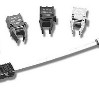
HFBR-0561
Description
KIT EVAL MT-RJ 155MB/S ATM M/S
Manufacturer
Avago Technologies US Inc.
Datasheet
1.HFBR-0555.pdf
(14 pages)
Specifications of HFBR-0561
Main Purpose
Interface, Ethernet
Embedded
No
Utilized Ic / Part
HFBR-5905(A)
Primary Attributes
MT-RJ 155Mb/s, Multimode and Singlemode Applications
Secondary Attributes
MT-RJ Fiber Connector Interface
Description/function
Fiber Optic Kit
For Use With/related Products
HFCT-5903E
Lead Free Status / RoHS Status
Contains lead / RoHS non-compliant
Lead Free Status / RoHS Status
Lead free / RoHS Compliant, Contains lead / RoHS non-compliant


Recommended Operating Conditions
Transmitter Electrical Characteristics
HFBR-5905 (T
HFBR-5905A (T
Receiver Electrical Characteristics
HFBR-5905 (T
HFBR-5905A (T
Notes:
B. Ambient Operating Temperature corresponds to transceiver case temperature of -40 °C mininum to +100 °C maximum with necessary
11
Parameter
Supply Voltage
Data Input Voltage - Low
Data Input Voltage - High
Data and Signal Detect Output Load
Differential Input Voltage (p-p)
Parameter
Supply Current
Power Dissipation
Data Input Current - Low
Data Input Current - High
Parameter
Supply Current
Power Dissipation
Data Output Voltage - Low
Data Output Voltage - High
Data Output Rise Time
Data Output Fall Time
Signal Detect Output Voltage - Low
Signal Detect Output Voltage - High
Signal Detect Output Rise Time
Signal Detect Output Fall Time
Power Supply Noise Rejection
Ambient Operating Temperature HFBR-5905
A. Ambient Operating Temperature corresponds to transceiver case temperature of 0 °C mininum to +85 °C maximum with necessary
airflow applied. Recommanded case temperature measurement point can be found in Figure 2.
airflow applied. Recommanded case temperature measurement point can be found in Figure 2.
A
A
A
A
= 0°C to +70°C, V
= 0°C to +70°C, V
= -40°C to +85°C, V
= -40°C to +85°C, V
HFBR-5905A
CC
CC
= 3.135 V to 3.465 V)
= 3.135 V to 3.465 V)
CC
CC
Symbol
R
Symbol
I
P
I
I
Symbol
I
P
PSNR
T
T
V
V
V
V
V
V
t
t
V
V
t
t
= 3.135 V to 3.465 V)
= 3.135 V to 3.465 V)
CC
IL
IH
CC
r
f
r
f
DISS
DISS
A
A
L
CC
IL
IH
D
OL
OH
OL
OH
- V
- V
- V
- V
- V
- V
CC
CC
CC
CC
CC
CC
Minimum Typical
0
-40
3.135
-1.810
-1.165
Minimum Typical
-350
Minimum Typical
-1.840
-1.045
0.35
0.35
-1.840
-1.045
0.35
0.35
133
18
50
0.800
0.45
-2
65
0.225
50
175
120
Maximum Unit
+70
+85
3.465
-1.475
-0.880
Maximum Unit
0.60
350
Maximum Unit
0.415
-1.620
-0.880
2.2
2.2
-1.620
-0.880
2.2
2.2
°C
°C
V
V
V
W
V
mA
µA
µA
mA
V
V
ns
ns
V
V
ns
ns
mV
W
W
Reference
Note A
Note B
Note 2
Reference
Note 3
Note 5a
Reference
Note 4
Note 5b
Note 6
Note 6
Note 7
Note 7
Note 6
Note 6
Note 7
Note 7
Related parts for HFBR-0561
Image
Part Number
Description
Manufacturer
Datasheet
Request
R

Part Number:
Description:
Fiber Optic Transmitters, Receivers, Transceivers 1300nm 155MBd 16-pin DIP ST Rx
Manufacturer:
Avago Technologies US Inc.

Part Number:
Description:
FIBER OPTIC TX 125 MBD 650N
Manufacturer:
Avago Technologies US Inc.
Datasheet:

Part Number:
Description:
Fiber Optic Evaluation Kit
Manufacturer:
Avago Technologies US Inc.
Datasheet:

Part Number:
Description:
RECEIVER FIBER OPTIC ST 266MBD
Manufacturer:
Avago Technologies US Inc.
Datasheet:

Part Number:
Description:
RCVR OPT HI SPEED VERS LINK HORZ
Manufacturer:
Avago Technologies US Inc.
Datasheet:

Part Number:
Description:
RCVR OPT HI SPEED VERS LINK VERT
Manufacturer:
Avago Technologies US Inc.
Datasheet:

Part Number:
Description:
TXRX OPTICAL 850NM VCSEL MT-RJ
Manufacturer:
Avago Technologies US Inc.
Datasheet:

Part Number:
Description:
TXRX MM SFP LC CONN BAIL DELATCH
Manufacturer:
Avago Technologies US Inc.
Datasheet:

Part Number:
Description:
TXRX MMF SFP GBE/FC BAIL DELATCH
Manufacturer:
Avago Technologies US Inc.
Datasheet:

Part Number:
Description:
XMITTER FIBER OPTIC 266MBD ST
Manufacturer:
Avago Technologies US Inc.
Datasheet:

Part Number:
Description:
OPTOCOUPLER GATE DRV 2A 16-SOIC
Manufacturer:
Avago Technologies US Inc.
Datasheet:
Part Number:
Description:
OPTOCOUPLER 2CH 2.5A 16-SOIC
Manufacturer:
Avago Technologies US Inc.
Datasheet:

Part Number:
Description:
OPTOCOUPLER GATE DRV 0.4A 16SOIC
Manufacturer:
Avago Technologies US Inc.
Datasheet:

Part Number:
Description:
OPTOCOUPLER 2.0A 250KHZ 8-DIP
Manufacturer:
Avago Technologies US Inc.
Datasheet:

Part Number:
Description:
OPTOCOUPLER 2.0A 250KHZ GW 8-SMD
Manufacturer:
Avago Technologies US Inc.
Datasheet: