CDB42L51 Cirrus Logic Inc, CDB42L51 Datasheet - Page 6
CDB42L51
Manufacturer Part Number
CDB42L51
Description
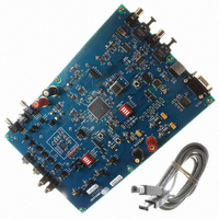
BOARD EVAL FOR CS42L51 CODEC
Manufacturer
Cirrus Logic Inc
Specifications of CDB42L51
Main Purpose
Audio, CODEC
Embedded
Yes, Other
Utilized Ic / Part
CS42L51, CS8406, CS8415
Primary Attributes
Stereo, Digital Audio Transmitter and Receiver
Secondary Attributes
Graphic User Interface, S/PDIF Interface
Description/function
Audio CODECs
Operating Supply Voltage
5 V
Product
Audio Modules
For Use With/related Products
CS42L51
Lead Free Status / RoHS Status
Contains lead / RoHS non-compliant
Lead Free Status / RoHS Status
Lead free / RoHS Compliant, Contains lead / RoHS non-compliant
Other names
598-1005


6
1.9
1.10
1.11
1.12
Analog Input
RCA connectors supply the line-level analog inputs through an AC-coupled passive filter. The signal from
these inputs may be driven to individual inputs or to all inputs of the CS42L51. A microphone may be con-
nected to one or both of the 1/8th inch jacks, MIC1 and MIC2.
To accommodate the microphone bias output available on certain input pins of the CS42L51, additional
stake headers are provided to MUX both the input audio signal and the output bias signal to or from the
CS42L51.
provides more details for how to connect the jumpers. The CS42L51 data sheet details the required single-
ended signal amplitude that will drive the inputs to full scale.
Analog Outputs
RCA connectors are connected directly to the output of the CS42L51 to allow evaluation of the ground-cen-
tered analog outputs. The Right Channel and Left Channel stake headers optionally connect a passive-fil-
tered output to the RCA connectors. For evaluation of the CS42L51’s drive strength into a load, the 16 Ω
HP Load stake headers connect the analog outputs to 16 Ω. Headphones may also be connected to the
1/8th inch jack. When connecting headphones, the 16 Ω load resistors should be disconnected by removing
the jumpers on each stake header.
One of the analog outputs may be connected to a speaker driver through the “Speaker” stake header. A
mono speaker may then be driven via the red and black banana jack. The red banana jack designates the
positive terminal while black designates the negative.
Stand-Alone Switches
The “FPGA H/W Control” and “CS42L51 H/W Control” switches control all Hardware Mode options.
Section 3. “Hardware Mode Control” on page 13
USB and RS-232 Control Port Connectors
A graphical user interface is available for the CDB42L51, allowing easy manipulation of each register. This
GUI interfaces with the CDB via the USB and RS-232 connectors and controls all Software Mode options.
Section 2. “Software Mode Control” on page 7
Simply connect a cable from the USB or RS-232 connector to the PC and launch the Cirrus Logic FlexGUI
software to enable software control of the CDB42L51.
Figure 18 on page 20
in the schematic set illustrates how signals are routed.
provides a description of the Graphical User Interface (GUI).
provides a description of each topology.
Table 4 on page 18
CDB42L51
DS679DB2
Related parts for CDB42L51
Image
Part Number
Description
Manufacturer
Datasheet
Request
R

Part Number:
Description:
Development Kit
Manufacturer:
Cirrus Logic Inc
Datasheet:
Part Number:
Description:
Development Kit
Manufacturer:
Cirrus Logic Inc
Datasheet:


Part Number:
Description:
High-efficiency PFC + Fluorescent Lamp Driver Reference Design
Manufacturer:
Cirrus Logic Inc
Datasheet:
Part Number:
Description:
Development Kit
Manufacturer:
Cirrus Logic Inc
Datasheet:
Part Number:
Description:
Development Kit
Manufacturer:
Cirrus Logic Inc
Datasheet:

Part Number:
Description:
Development Kit
Manufacturer:
Cirrus Logic Inc
Datasheet:
Part Number:
Description:
Development Kit
Manufacturer:
Cirrus Logic Inc
Datasheet:
Part Number:
Description:
Development Kit
Manufacturer:
Cirrus Logic Inc
Datasheet:
Part Number:
Description:
Development Kit
Manufacturer:
Cirrus Logic Inc
Datasheet:

Part Number:
Description:
EVALUATION BOARD FOR CS8427
Manufacturer:
Cirrus Logic Inc
Datasheet:

Part Number:
Description:
BOARD EVAL FOR CS8416 RCVR
Manufacturer:
Cirrus Logic Inc
Datasheet:

Part Number:
Description:
EVALUATION BOARD FOR CS8420
Manufacturer:
Cirrus Logic Inc
Datasheet:

Part Number:
Description:
KIT DEVELOPMENT EP9315 ARM9
Manufacturer:
Cirrus Logic Inc
Datasheet:

Part Number:
Description:
KIT DEVELOPMENT EP9302 ARM9
Manufacturer:
Cirrus Logic Inc
Datasheet: