EVAL6206N STMicroelectronics, EVAL6206N Datasheet - Page 4
EVAL6206N
Manufacturer Part Number
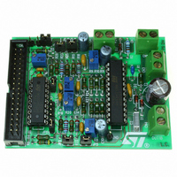
EVAL6206N
Description
EVAL BOARD FOR L6206N DIP
Manufacturer
STMicroelectronics
Specifications of EVAL6206N
Mfg Application Notes
PractiSPIN AppNote
Design Resources
EVAL6206N/6206N Gerber Files EVAL6206N Schematic/Bill of Materials
Main Purpose
Power Management, H Bridge Driver (Internal FET)
Embedded
No
Utilized Ic / Part
L6205N DIP
Primary Attributes
Dual Full-Bridge (H-Bridge), 2.8A (5.6A Peak). 8 ~ 52 V, 0.3 Ohm
Secondary Attributes
Non-Inverting, Can be Paralleled
Architecture
Analog
Applications
Motor Control
Processor To Be Evaluated
L6206
For Use With
497-4138 - EVALUATION BOARD PRACTISPIN
Lead Free Status / RoHS Status
Lead free / RoHS Compliant
Other names
497-5487


L6206
PIN DESCRIPTION
4/23
PowerDIP24
SO24/
18, 19
PIN #
6, 7,
10
11
12
13
14
15
16
17
20
21
1
2
3
4
5
8
9
PACKAGE
PowerSO36
19, 36
PIN #
1, 18,
10
11
12
13
15
22
24
25
26
27
28
29
30
32
33
4
5
PROGCL
SENSE
SENSE
VBOOT
OUT1
OUT1
OUT2
OUT2
Name
OCD
OCD
GND
IN1
IN2
IN1
IN2
EN
VS
VS
B
A
B
A
A
B
B
A
B
A
B
B
A
A
B
B
Power Supply
Power Supply
Power Supply
Power Supply
Power Output
Power Output
Power Output
Power Output
Open Drain
Open Drain
Logic Input
Logic Input
Logic Input
Logic input
Logic input
Voltage
Supply
Output
Output
R Pin
Type
GND
Bridge A Logic Input 1.
Bridge A Logic Input 2.
Bridge A Source Pin. This pin must be connected to Power
Ground directly or through a sensing power resistor.
Bridge A Overcurrent Detection and thermal protection pin.
An internal open drain transistor pulls to GND when
overcurrent on bridge A is detected or in case of thermal
protection.
Bridge A Output 1.
Signal Ground terminals. In Power DIP and SO packages,
these pins are also used for heat dissipation toward the
PCB.
Bridge B Output 1.
Bridge B Overcurrent Detection and thermal protection pin.
An internal open drain transistor pulls to GND when
overcurrent on bridge B is detected or in case of thermal
protection.
Bridge B Source Pin. This pin must be connected to Power
Ground directly or through a sensing power resistor.
Bridge B Input 1
Bridge B Input 2
Bridge B Overcurrent Level Programming. A resistor
connected between this pin and Ground sets the
programmable current limiting value for the bridge B. By
connecting this pin to Ground the maximum current is set.
This pin cannot be left non-connected.
Bridge B Enable. LOW logic level switches OFF all Power
MOSFETs of Bridge B.
If not used, it has to be connected to +5V.
Bootstrap Voltage needed for driving the upper Power
MOSFETs of both Bridge A and Bridge B.
Bridge B Output 2.
Bridge B Power Supply Voltage. It must be connected to
the supply voltage together with pin VS
Bridge A Power Supply Voltage. It must be connected to
the supply voltage together with pin VS
Bridge A Output 2.
Function
A
B
.
.
Related parts for EVAL6206N
Image
Part Number
Description
Manufacturer
Datasheet
Request
R

Part Number:
Description:
STMicroelectronics [RIPPLE-CARRY BINARY COUNTER/DIVIDERS]
Manufacturer:
STMicroelectronics
Datasheet:
Part Number:
Description:
STMicroelectronics [LIQUID-CRYSTAL DISPLAY DRIVERS]
Manufacturer:
STMicroelectronics
Datasheet:

Part Number:
Description:
BOARD EVAL FOR MEMS SENSORS
Manufacturer:
STMicroelectronics
Datasheet:
Part Number:
Description:
NPN TRANSISTOR POWER MODULE
Manufacturer:
STMicroelectronics
Datasheet:
Part Number:
Description:
TURBOSWITCH ULTRA-FAST HIGH VOLTAGE DIODE
Manufacturer:
STMicroelectronics
Datasheet:
Part Number:
Description:
Manufacturer:
STMicroelectronics
Datasheet:
Part Number:
Description:
DIODE / SCR MODULE
Manufacturer:
STMicroelectronics
Datasheet:
Part Number:
Description:
DIODE / SCR MODULE
Manufacturer:
STMicroelectronics
Datasheet:
Part Number:
Description:
Search -----> STE16N100
Manufacturer:
STMicroelectronics
Datasheet:
Part Number:
Description:
Search ---> STE53NA50
Manufacturer:
STMicroelectronics
Datasheet:
Part Number:
Description:
NPN Transistor Power Module
Manufacturer:
STMicroelectronics
Datasheet:
Part Number:
Description:
DIODE / SCR MODULE
Manufacturer:
STMicroelectronics
Datasheet: