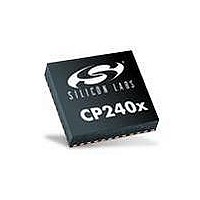
CP2400AB Silicon Laboratories Inc, CP2400AB Datasheet - Page 82

CP2400AB
Manufacturer Part Number
CP2400AB
Description
BOARD EVAL SPI LCD DRIVER CP2400
Manufacturer
Silicon Laboratories Inc
Specifications of CP2400AB
Main Purpose
LCD Development
Embedded
No
Utilized Ic / Part
CP2400
Primary Attributes
I²C, SMBus Interfaces
Secondary Attributes
Up to 128 segments
Product
Microcontroller Accessories
Core Processor
CP2400
Clock Speed
20 MHz
Interface Type
SPI
Timers
2
Operating Supply Voltage
1.8 V to 3.6 V
Cpu Core
CP2400
Lead Free Status / RoHS Status
Contains lead / RoHS non-compliant
Lead Free Status / RoHS Status
Lead free / RoHS Compliant, Contains lead / RoHS non-compliant
Other names
336-1857
CP2400/1/2/3
Internal Register Definition 11.7. CAPTUREn: SmaRTClock Timer Capture
SmaRTClock AddressCAPTURE0 = 0x00; CAPTURE1 = 0x01; CAPTURE2 =0x02; CAPTURE3: 0x03.
Internal Register Definition 11.8. ALARMn: SmaRTClock Alarm Programmed Value
SmaRTClock AddressALARM0 = 0x08; ALARM1 = 0x09; ALARM2 = 0x0A; ALARM3 = 0x0B
82
Note: The least significant bit of the timer capture value is in CAPTURE0.0.
Note: The least significant bit of the alarm programmed value is in ALARM0.0.
Name
Reset
Name
Reset
7:0
7:0
Bit
Bit
Type
Type
Bit
Bit
CAPTURE[31:0] SmaRTClock Timer Capture.
ALARM[31:0] SmaRTClock Alarm Programmed Value.
Name
Name
R/W
R/W
7
0
7
0
These 4 registers (ALARM3–ALARM0) are used to set an alarm event for the SmaRTClock
timer. The SmaRTClock alarm should be disabled (RTC0AEN=0) when updating these reg-
isters.
These 4 registers (CAPTURE3–CAPTURE0) are used to read or set the 32-bit SmaRT-
Clock timer. Data is transferred to or from the SmaRTClock timer when the RTC0SET or
RTC0CAP bits are set.
R/W
R/W
6
0
6
0
R/W
R/W
5
0
5
0
Rev. 1.0
R/W
R/W
CAPTURE[31:0]
4
0
4
0
ALARM[31:0]
Function
Function
R/W
R/W
3
0
3
0
R/W
R/W
2
0
2
0
R/W
R/W
1
0
1
0
R/W
R/W
0
0
0
0


