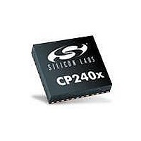
CP2400AB Silicon Laboratories Inc, CP2400AB Datasheet - Page 9

CP2400AB
Manufacturer Part Number
CP2400AB
Description
BOARD EVAL SPI LCD DRIVER CP2400
Manufacturer
Silicon Laboratories Inc
Specifications of CP2400AB
Main Purpose
LCD Development
Embedded
No
Utilized Ic / Part
CP2400
Primary Attributes
I²C, SMBus Interfaces
Secondary Attributes
Up to 128 segments
Product
Microcontroller Accessories
Core Processor
CP2400
Clock Speed
20 MHz
Interface Type
SPI
Timers
2
Operating Supply Voltage
1.8 V to 3.6 V
Cpu Core
CP2400
Lead Free Status / RoHS Status
Contains lead / RoHS non-compliant
Lead Free Status / RoHS Status
Lead free / RoHS Compliant, Contains lead / RoHS non-compliant
Other names
336-1857
4. Hardware Setup using a USB Debug Adapter
The target board is connected to a PC running the Silicon Laboratories IDE via the USB Debug Adapter as shown
in Figure 9.
1. Connect the LCD development board to the F930 target board as shown in Figure 8.
2. Connect the USB Debug Adapter to the DEBUG connector on the C8051F930 target board with the 10-pin
3. Connect one end of the USB cable to the USB connector on the USB Debug Adapter.
4. Connect the other end of the USB cable to a USB Port on the PC.
5. Verify that a shorting block is installed on J17 and that SW5 is in the ON position on the C8051F930 target
6. Verify that a shorting block is installed on J2 of the CP2400/1 LCD Development Board.
7. Connect the ac/dc power adapter to power jack P1 on the C8051F930 target board (Optional).
Notes:
LCD Development Board
ribbon cable.
board.
Use the Reset button in the IDE to reset the target when connected using a USB Debug Adapter.
Remove power from the target board and the USB Debug Adapter before connecting or disconnecting the
ribbon cable from the target board. Connecting or disconnecting the cable when the devices have power can
damage the device and/or the USB Debug Adapter.
J1
J5
DEVELOPMENT BOARD
U1
CP2400-GQ LCD
CP2400
D1
LED
www.silabs.com
SILICON LABS
IMEASURE
D2
PWR
J2
J1
J5J4
J5
DEVELOPMENT BOARD
U1
CP2400-GQ LCD
CP2400
P1
D1
LED
www.silabs.com
SILICON LABS
Figure 8. CP2400/1 LCD Development Board Attachment
IMEASURE
Figure 9. Hardware Setup Using a USB Debug Adapter
D2
PWR
J2
H1
R15
J5J4
J16
J15
J6 VDD/DC+
TOUCH SENSE SWITCH
J4
J3
J5
P2.0
SILICON LABS
Target Board
J7
www.silabs.com
P1
TOUCH SENSE SWITCH
F930
U1
P2.1
`
OFF
ON
J2
J13
J14
SW5
J8
P1.6
P1.5
IMEASURE
AAA_BAT
RESET
COIN_CELL
WALL_PWR
J17
H2
H1
R15
USB POWER
P0.2
+1VD
+3VD
Rev. 0.1
J16
VBAT
J11
2103
J1
VBAT
CP
U3
P0.3
J15
J12
P2
P3
SW4
J9
J6
TOUCH SENSE SWITCH
J4
J3
VDD/DC+
J5
P2.0
SILICON LABS
USB Debug
J7
www.silabs.com
Adapter
TOUCH SENSE SWITCH
F930
U1
P2.1
`
OFF
Adapter
ON
J2
AC/DC
J13
J14
SW5
J8
P1.5
P1.6
IMEASURE
AAA_BAT
RESET
COIN_CELL
WALL_PWR
J17
H2
CP2400/1-DK
USB POWER
P0.2
+3VD
+1VD
VBAT
J11
Cable
2103
J1
USB
VBAT
U3
CP
P0.3
J12
P2
P3
SW4
J9
PC
9


