KIT34676EPEVBE Freescale Semiconductor, KIT34676EPEVBE Datasheet
KIT34676EPEVBE
Specifications of KIT34676EPEVBE


Related parts for KIT34676EPEVBE

KIT34676EPEVBE Summary of contents
Page 1
... Freescale Semiconductor User’s Guide Using the High Input Voltage Charger for Single Cell Li-Ion Batteries (KIT34676EPEVBE) 1 Purpose This User Guide helps the Lithium-Ion (Li-Ion) battery charger designer understand the MC34676B and its evaluation board. It illustrates the design procedure when using the MC34676B to design a Li-Ion battery charger, and the way to get the best performance from the MC34676B ...
Page 2
... ISET Figure 1. The dual-input Li-Ion Charger Figure 2 is the typical application circuit. MC34676B AC BAT BATDET USB USBOUT GND IMIN PPR CHG IUSB ISET USBEN R R IUSB ISET AC Figure 1 is the typical application circuit. Two VDDIO MCU USB Rev. 1.0 Freescale Semiconductor ...
Page 3
... BAT R 4 TP7 _1X2 00K 1 00K TP1 0 VLo gic 1 TP1 TP2 TP1 3 U SBE SBE N 1 Figure 3. The Schematic Circuit of the Evaluation Board Using the Dual 28V Input Voltage Charger with Linear Regulator, Freescale Semiconductor = 5.85V EEN 676 TP2 BAT / SBOU ...
Page 4
... A metal film with a 1% tolerance resistor should be used for USB Table 2 shows the charge current with the different settings of pin headers J10 and J11. J10 J11 Charge Current 150mA 450mA 750mA 1050mA Charge Current Rev. 1.0 Freescale Semiconductor Eqn. 1 Eqn. 2 ...
Page 5
... The end-of-charge (EOC) current for both the AC charger and the USB charger can be set by the resistors R10 and R11. On the evaluation board, two resistors with one pin header jumper are used for the user to conveniently configure different EOC current values. Using the Dual 28V Input Voltage Charger with Linear Regulator, Freescale Semiconductor Open Open Short ...
Page 6
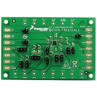
... Layout Design 6 Layout Design 6.1 Layout The KIT34676EPEVBE PCB board has two copper layers. The component side of the KIT34676EPEVBE is provided to locate all components. Figure 4 Figure 4. The Overview of the Evaluation Board Figure 5. The Component Side Silkscreen Layer of the Evaluation Board Using the Dual 28V Input Voltage Charger with Linear Regulator overview of the board, followed by the layout of each layer ...
Page 7
... Figure 6. The Component Side Layer of the Evaluation Board Figure 7. The Solder Side Layer of the Evaluation Board Using the Dual 28V Input Voltage Charger with Linear Regulator, Freescale Semiconductor Layout Design Rev. 1.0 7 ...
Page 8
... To get better thermal performance, put the EPAD pin of the MC34676B on a large ground plane on the component side, and use a via array to connect the EPAD pin to the ground layer, or the large ground plane on the other layer. Using the Dual 28V Input Voltage Charger with Linear Regulator, 8 Rev. 1.0 Freescale Semiconductor ...
Page 9
... The J13 pin header allows the user to choose the AC charger when leaving it open, the USB charger is chosen when shorting pins 1 and 2. The default settings of the evaluation board are shown in Using the Dual 28V Input Voltage Charger with Linear Regulator, Freescale Semiconductor Table 4, which selects the AC charger of MC34676B. Table 4. The Default Settings of the Pin Headers ...
Page 10
... MC34676B. The VBAT pad connects the positive pole of the Li+ battery being charged. 7.3 Test Points The KIT34676EPEVBE evaluation board provides 11 signal test points and 3 ground test points for users to conveniently hook up multi-meters and oscilloscope probes to evaluate the MC34676B. The test points connect the pins of the MC34676B with the same names directly. ...
Page 11
... Figure 8. The AC Charger Set Up for the Evaluation Board USB Power Port Figure 9. The USB Charger Set Up for the Evaluation Board Using the Dual 28V Input Voltage Charger with Linear Regulator, Freescale Semiconductor and Figure 9. Connect a DC power source with a larger than 2.0A current limit ...
Page 12
... LITE ON LTST-C190KGKT TYCO ELEC- 826629-2 TRONICS TYCO ELEC- 826629-3 TRONICS KOA SPEER RK73H1JTTD2612F KOA SPEER RK73H1JTTD1302F KOA SPEER RK73H1JTTD6491F BOURNS CR0603JW471E BOURNS CR0603-JW-104ELF KOA SPEER RK73H1JTTD1332F KOA SPEER RK73H1JTTD2872F KOA SPEER RK73H1JTTD2003F N/A COMPONENTS TP-105-01-00 CORPORATION Freescale Rev. 1.0 Freescale Semiconductor ...
Page 13
... Following are URLs where you can obtain information on other Freescale products and application solutions: Products Data Sheet MC34676 Freescale’s Web Site Freescale’s Analog Web Site Freescale’s Power Management Using the Dual 28V Input Voltage Charger with Linear Regulator, Freescale Semiconductor Links www.freescale.com/files/analog/doc/data_sheet/MC34676.pdf www.freescale.com www.freescale.com/analog www.freescale.com/powermanagement References Rev. 1.0 ...
Page 14
... Freescale Semiconductor product could create a situation where personal injury or death may occur. Should Buyer ...