KIT33932VWEVBE Freescale Semiconductor, KIT33932VWEVBE Datasheet - Page 7
KIT33932VWEVBE
Manufacturer Part Number
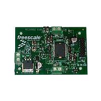
KIT33932VWEVBE
Description
KIT EVALUATION FOR MC33932
Manufacturer
Freescale Semiconductor
Type
MOSFET & Power Driverr
Datasheets
1.KIT33932VWEVBE.pdf
(16 pages)
2.KIT33932VWEVBE.pdf
(21 pages)
3.KIT33932VWEVBE.pdf
(16 pages)
Specifications of KIT33932VWEVBE
Main Purpose
Power Management, Motor Control
Embedded
No
Utilized Ic / Part
MC33932
Primary Attributes
1 H-Bridge Driver
Secondary Attributes
USB, I2C, SPI Interface
Interface Type
USB, SPI
Product
Power Management Modules
Silicon Manufacturer
Freescale
Silicon Core Number
MC33932
Kit Application Type
Power Management
Application Sub Type
Switch
Kit Contents
Evaluation Board, CD, Misc Cables
Rohs Compliant
Yes
Lead Free Status / RoHS Status
Lead free / RoHS Compliant
For Use With/related Products
MC33932


Table 3. Static Electrical Characteristics (continued)
values noted reflect the approximate parameter means at T
Specifications given for H-Bridge A apply symmetrically to H-Bridge B.
Analog Integrated Circuit Device Data
Freescale Semiconductor
POWER OUTPUTS OUT1, OUT2
HIGH SIDE CURRENT SENSE FEEDBACK
Notes
STATUS FLAG
Output-ON Resistance
Output Current Regulation Threshold
High Side Short Circuit Detection Threshold (Short Circuit to Ground)
Low Side Short Circuit Detection Threshold (Short Circuit to V
Output Leakage Current
Output MOSFET Body Diode Forward Voltage Drop, I
Over-temperature Shutdown
Current Foldback at T
Current Foldback to Thermal Shutdown Separation
Feedback Current (pin FB sourcing current)
Status Flag Leakage Current
Status Flag SET Voltage
13.
14.
15.
16.
17.
18.
19.
Characteristics noted under conditions 8.0 V ≤ V
V
V
V
T
T
V
V
Thermal Limit
Hysteresis
I
I
I
I
I
I
V
I
OUT
OUT
OUT
OUT
OUT
OUT
SF
J
J
PWR
PWR
PWR
OUT
OUT
SF
< T
≥ T
This parameter is Guaranteed By Design.
Output-ON resistance as measured from output to
Outputs switched OFF via D1 or EN/D2.
Accuracy is better than 20% from 0.5 A to 6.0 A. Recommended terminating resistor value: R
Status Flag output is an open drain output requiring a pull-up resistor to logic V
Status Flag Leakage Current is measured with Status Flag HIGH and not SET.
Status Flag Set Voltage measured with Status Flag LOW and SET with I
< 500 μA . Maximum allowable pull-up voltage < 7.0 V.
= 300 µA
= 5.0 V
= 0 mA
= 300 mA
= 500 mA
= 1.5 A
= 3.0 A
= 6.0 A
FB
FB
=
= Ground
= 8.0 V, T
= 8.0 V, T
= 5.0 V, T
V
(Fold back Region - see
PWR
@
(17)
T
@
J
J
J
J
T
= 25
= 150
= 150
J
J
(14)
(13)
(15)
(19)
°
, I
C
°
°
C
C
, Outputs off, V
Characteristic
LOAD
(13)
(18)
= 3.0 A
Figure 9
PWR
(16)
and
= 28 V
Figure
(13)
OUT
PWR
11)
V
= 3.0 A
PWR and from output to GND.
≤ 28 V, - 40°C ≤ T
(13)
PWR
A
)
(13)
= 25°C under nominal conditions, unless otherwise noted.
(13)
I
R
Symbol
OUTLEAK
V
I
SFLEAK
T
SFLOW
DS(ON)
T
SF
I
I
T
I
T
A
SCH
I
SCL
LIM
V
HYS
SEP
LIM
FB
FB
≤ 125°C, GND = 0 V, unless otherwise noted. Typical
F
= 300 μA. Maximum allowable sink current from this pin is
DD
.
11.43
0.35
2.86
5.71
Min
–60
175
165
5.2
9.0
0.0
0.0
11
10
STATIC ELECTRICAL CHARACTERISTICS
–
–
–
–
–
–
–
–
–
FB
= 270 Ω.
ELECTRICAL CHARACTERISTICS
0.775
14.29
3.57
7.14
Typ
120
270
6.5
4.2
13
11
12
–
–
–
–
–
–
–
–
–
–
–
17.15
Max
1.56
4.28
8.57
235
325
100
200
185
750
8.0
2.0
5.0
0.4
16
14
15
50
–
–
–
–
Unit
mΩ
mA
mA
mA
mA
μA
μA
μA
μA
°C
°C
°C
A
A
A
V
V
33932
7
Related parts for KIT33932VWEVBE
Image
Part Number
Description
Manufacturer
Datasheet
Request
R

Part Number:
Description:
Manufacturer:
Freescale Semiconductor, Inc
Datasheet:
Part Number:
Description:
Manufacturer:
Freescale Semiconductor, Inc
Datasheet:
Part Number:
Description:
Manufacturer:
Freescale Semiconductor, Inc
Datasheet:
Part Number:
Description:
Manufacturer:
Freescale Semiconductor, Inc
Datasheet:
Part Number:
Description:
Manufacturer:
Freescale Semiconductor, Inc
Datasheet:
Part Number:
Description:
Manufacturer:
Freescale Semiconductor, Inc
Datasheet:
Part Number:
Description:
Manufacturer:
Freescale Semiconductor, Inc
Datasheet:
Part Number:
Description:
Manufacturer:
Freescale Semiconductor, Inc
Datasheet:
Part Number:
Description:
Manufacturer:
Freescale Semiconductor, Inc
Datasheet:
Part Number:
Description:
Manufacturer:
Freescale Semiconductor, Inc
Datasheet:
Part Number:
Description:
Manufacturer:
Freescale Semiconductor, Inc
Datasheet:
Part Number:
Description:
Manufacturer:
Freescale Semiconductor, Inc
Datasheet:
Part Number:
Description:
Manufacturer:
Freescale Semiconductor, Inc
Datasheet:
Part Number:
Description:
Manufacturer:
Freescale Semiconductor, Inc
Datasheet:
Part Number:
Description:
Manufacturer:
Freescale Semiconductor, Inc
Datasheet: