KIT34671EPEVBE Freescale Semiconductor, KIT34671EPEVBE Datasheet
KIT34671EPEVBE
Specifications of KIT34671EPEVBE


Related parts for KIT34671EPEVBE

KIT34671EPEVBE Summary of contents
Page 1
... Freescale Semiconductor User’s Guide Using the High Input Voltage Charger for Single Cell Li-Ion Batteries (KIT34671EPEVBE) 1 Purpose This User Guide helps the Lithium-Ion (Li-Ion) battery charger designer understand the MC34671 and its evaluation board. It illustrates the design procedure when using the MC34671 to design a Li-Ion battery charger, and the way to get the best performance from the MC34671 ...
Page 2
... C IN MC34671 GND ISET CHG PPR FAST EN Figure 1. The Standalone Li-Ion Charger BAT VIN C OUT GND MC34671 ISET CHG PPR FAST EN OFF ON Figure 1 is the typical application C OUT Li+ R ISET Figure 2 V Li+ IO 100Kx3 MCU Batteries, Rev. 1.0 Freescale Semiconductor is the ...
Page 3
... C3 CC0603 1.0µF C4 CC1206 47µF C5 CC1206 47µF C6 CC1206 47µF R1 RC0603 470 R2 RC0603 470 Using the High Input Voltage Charger for Single Cell Li-Ion Freescale Semiconductor shows its schematic circuit. TP1 TP2 TP7 C1 1.0uF BAT D1 GREEN R1 470 OHM PPR BAT 3 7 CHG ...
Page 4
... Single Cell Li+ Battery Charger IC, Linear Batteries, Rev. 1.0 Vendor BOURNS BOURNS BOURNS KOA SPEER KOA SPEER KOA SPEER LITE ON LITE ON COMPONENTS COMPONENTS COMPONENTS COMPONENTS COMPONENTS COMPONENTS COMPONENTS COMPONENTS COMPONENTS COMPONENTS TYCO TYCO TYCO TYCO TYCO TYCO TYCO TYCO TYCO FREESCALE Freescale Semiconductor ...
Page 5
... On the evaluation board, three resistors with two pin header jumpers are used for the user to conveniently configure different charge current values. the different settings of pin headers JP7 and JP8. Using the High Input Voltage Charger for Single Cell Li-Ion Freescale Semiconductor is in units of amps. A metal film with a 1% tolerance resistor CHG Table 2 Table 2 ...
Page 6
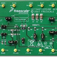
... Layout Design 6.1 Layout The KIT34671EPEVBE PCB board has two copper layers. The component side of the KIT34671EPEVBE is provided to locate all components. followed by the layout of each layer. Figure 4. The Overview of the Evaluation Board Using the High Input Voltage Charger for Single Cell Li-Ion ...
Page 7
... Figure 5. The Silkscreen Layer of the Evaluation Board Figure 6. The Component Side Layer of the Evaluation Board Using the High Input Voltage Charger for Single Cell Li-Ion Freescale Semiconductor Layout Design Batteries, Rev. 1.0 7 ...
Page 8
... The JP2 pin header selects the voltage to supply the D1 and D2 LED indicators. Shorting pins 1 and 2 selects VIN to power the LEDs. Shorting pins 2 and 3 selects the BAT pin to power the LEDs. Using the High Input Voltage Charger for Single Cell Li-Ion 8 Batteries, Rev. 1.0 Freescale Semiconductor ...
Page 9
... When using the evaluation board to connect to the system, please apply the required I/O logic voltage at the VL pad of the evaluation board and set the pin header jumpers as shown in Table 4. Using the High Input Voltage Charger for Single Cell Li-Ion Freescale Semiconductor Table 3. Default Setting Shorted ...
Page 10
... Using the High Input Voltage Charger for Single Cell Li-Ion 10 Pin Header Jumpers Default Setting JP1 Shorted JP2 Open JP3 Open JP4 Shorted JP5 Shorted JP6 Shorted JP7 Shorted JP8 Shorted JP9 2 and 3 shorted 8. Connect a DC power source with a larger than 1.0A current Batteries, Rev. 1.0 Freescale Semiconductor ...
Page 11
... DC Power Source Figure 8. The Test Set Up for the Evaluation Board Using the High Input Voltage Charger for Single Cell Li-Ion Freescale Semiconductor Test Setup with the Evaluation Board Li+ Battery Batteries, Rev. 1.0 11 ...
Page 12
... References 9 References • MC34671PG Quick Reference • MC34671 Data Sheet Using the High Input Voltage Charger for Single Cell Li-Ion 12 Batteries, Rev. 1.0 Freescale Semiconductor ...
Page 13
... Freescale Semiconductor product could create a situation where personal injury or death may occur. Should Buyer ...