KIT34673EPEVBE Freescale Semiconductor, KIT34673EPEVBE Datasheet - Page 15
KIT34673EPEVBE
Manufacturer Part Number
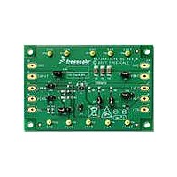
KIT34673EPEVBE
Description
KIT EVALUATION FOR MC34673
Manufacturer
Freescale Semiconductor
Type
Battery Managementr
Specifications of KIT34673EPEVBE
Main Purpose
Power Management, Battery Charger
Embedded
No
Utilized Ic / Part
MC34673
Primary Attributes
1 Cell- Li-Ion
Secondary Attributes
LED Status Indicators
Input Voltage
2.6 V
Maximum Operating Temperature
+ 85 C
Minimum Operating Temperature
- 40 C
Product
Power Management Modules
Supply Current
1.2 A
Silicon Manufacturer
Freescale
Silicon Core Number
MC34673
Kit Application Type
Power Management - Battery
Application Sub Type
Battery Charger
Kit Contents
Evaluation Board, CD
Rohs Compliant
Yes
Lead Free Status / RoHS Status
Lead free / RoHS Compliant
For Use With/related Products
MC34673


the ISET pin voltage to monitor the actual charge current as
given in
CHARGE CURRENT LIMITATION
battery (V
R
less than the programmed CC-mode current I
charge current is limited by (V
battery is too high, the large power dissipation may lead to
the charge-current thermal-foldback operation due to the die
temperature regulation. The charge current is reduced to
prevent further temperature rise (See
Thermal
DC INPUT VOLTAGE
following conditions are satisfied, the input is in a power-good
range for the charger to start charging. The conditions
include:
where V
monitors the input and the battery voltages. The V
preventing the reverse leakage current from the battery when
the power supply is off. V
threshold. When the DC input voltage is above the over-
voltage protection threshold, the charger is disabled
internally. The 28V input voltage rating eliminates the need of
any additional input over-voltage protection circuitry.
CHARGE-ENABLE INPUT
down current. Driving it to a low logic voltage, leaving it
floating, or shorting it to the ground will enable the charger, if
the input voltage is in the power-good range. Whenever the
EN pin is driven to a high logic voltage, the charger is
disabled.
Analog Integrated Circuit Device Data
Freescale Semiconductor
DS(ON)
1. V
2. V
3. V
The charge current is limited by multiple factors.
When the voltage difference between the input and the
When the voltage difference between the input and the
The MC34673 accepts up to 28V DC input. When all of the
The charge-enable input, EN, has a weak internal pull-
IN
IN
IN
OS
equ. 1
is the on resistance of the power MOSFET, may be
Foldback).
> V
- V
< V
IN
is the offset voltage for the comparator that
- V
BAT
POR
OVP
BAT
during the whole charging cycle.
> V
) is low, (V
OS
OVP
IN
IN
is the over-voltage protection
- V
- V
BAT
BAT
) / R
) / R
Charge Current
DS(ON)
DS(ON)
CHG
in this case.
, where
. The
OS
is for
INPUT POWER PRESENCE INDICATOR
When V
reset voltage threshold (V
voltage to indicate the input power presence. The PPR out-
put is only controlled by the input voltage. All other functions,
such as the EN pin, the over-voltage protection, and the VIN-
BAT comparator, do not affect the PPR output. The PPR pin
is capable to sink at least 12.0mA current when outputting a
low voltage to drive an external LED.
CHARGE STATUS INDICATORS
FAST. CHG outputs a low voltage when the charger is
enabled and the charging is in progress. When the charge
cycle completes, CHG outputs high-impedance. If the
charger is disabled or the input voltage is out of the power-
good range, the CHG pin outputs high-impedance as well.
The CHG pin has at least 12.0mA current-sinking capability
to drive an external LED, same as the PPR pin.
mode or not. When the charger is on and the battery voltage
is higher than the trickle-mode threshold, the charger enters
the fast-charge mode and FAST outputs a low voltage. The
open-drain FAST pin requires a pull-up resistor to output the
logic signal. If the charger is in the trickle-charge mode or is
disabled, or when the input voltage is out of the power-good
range, the FAST pin outputs high-impedance.
CHARGE CURRENT THERMAL FOLDBACK
charge current when the die temperature reaches 110°C to
prevent further temperature rise. This feature protects the
MC34673 from over-temperature failures and allows the user
to push the limits of the power handling capability of a given
circuit board without the risk of damaging the MC34673. The
charge current can be programmed according to the typical
(not the worst-case) ambient temperature with the assurance
that the charger will automatically reduce the current in worst-
case conditions.
The MC34673 has two charge status indicators, CHG and
FAST indicates whether the MC34673 is in the fast-charge
An internal thermal feedback loop begins to reduce the
IN
is applied and the voltage is above the power-on-
POR
FUNCTIONAL DEVICE OPERATION
), the PPR pin outputs a low
OPERATIONAL MODES
34673
15
Related parts for KIT34673EPEVBE
Image
Part Number
Description
Manufacturer
Datasheet
Request
R

Part Number:
Description:
Manufacturer:
Freescale Semiconductor, Inc
Datasheet:
Part Number:
Description:
Manufacturer:
Freescale Semiconductor, Inc
Datasheet:
Part Number:
Description:
Manufacturer:
Freescale Semiconductor, Inc
Datasheet:
Part Number:
Description:
Manufacturer:
Freescale Semiconductor, Inc
Datasheet:
Part Number:
Description:
Manufacturer:
Freescale Semiconductor, Inc
Datasheet:
Part Number:
Description:
Manufacturer:
Freescale Semiconductor, Inc
Datasheet:
Part Number:
Description:
Manufacturer:
Freescale Semiconductor, Inc
Datasheet:
Part Number:
Description:
Manufacturer:
Freescale Semiconductor, Inc
Datasheet:
Part Number:
Description:
Manufacturer:
Freescale Semiconductor, Inc
Datasheet:
Part Number:
Description:
Manufacturer:
Freescale Semiconductor, Inc
Datasheet:
Part Number:
Description:
Manufacturer:
Freescale Semiconductor, Inc
Datasheet:
Part Number:
Description:
Manufacturer:
Freescale Semiconductor, Inc
Datasheet:
Part Number:
Description:
Manufacturer:
Freescale Semiconductor, Inc
Datasheet:
Part Number:
Description:
Manufacturer:
Freescale Semiconductor, Inc
Datasheet:
Part Number:
Description:
Manufacturer:
Freescale Semiconductor, Inc
Datasheet: