SOUNDBITE Freescale Semiconductor, SOUNDBITE Datasheet - Page 17
SOUNDBITE
Manufacturer Part Number
SOUNDBITE
Description
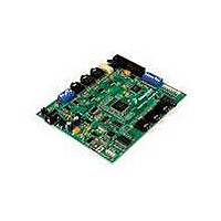
BOARD DEMO AUDIO DEVELOPMENT
Manufacturer
Freescale Semiconductor
Series
Symphony™ soundBiter
Datasheet
1.DSPB56371AF180.pdf
(68 pages)
Specifications of SOUNDBITE
Main Purpose
Audio, Audio Processing
Utilized Ic / Part
DSPB56371
Primary Attributes
Up to 8 channels of digital audio
Secondary Attributes
USB, I2C, SPI Interface
Processor To Be Evaluated
DSP56371
Data Bus Width
24 bit
Interface Type
USB
Lead Free Status / RoHS Status
Lead free / RoHS Compliant
Embedded
-
Lead Free Status / Rohs Status
Lead free / RoHS Compliant


Freescale Semiconductor
Signal
Name
MISO
SCK
SDA
SCL
Signal Type
open-drain
Input or
Input or
Input or
Input or
output
output
output
output
Tri-stated SPI Serial Clock—The SCK signal is an output when the SPI is configured as a
Tri-stated SPI Master-In-Slave-Out—When the SPI is configured as a master, MISO is the
during
Reset
State
Table 7. Serial Host Interface Signals
master and a Schmitt-trigger input when the SPI is configured as a slave. When
the SPI is configured as a master, the SCK signal is derived from the internal SHI
clock generator. When the SPI is configured as a slave, the SCK signal is an
input, and the clock signal from the external master synchronizes the data
transfer. The SCK signal is ignored by the SPI if it is defined as a slave and the
slave select (SS) signal is not asserted. In both the master and slave SPI devices,
data is shifted on one edge of the SCK signal and is sampled on the opposite
edge where data is stable. Edge polarity is determined by the SPI transfer
protocol.
I
SCL is a Schmitt-trigger input when configured as a slave and an open-drain
output when configured as a master. SCL should be connected to V
pull-up resistor.
This signal is tri-stated during hardware, software and individual reset. Thus,
there is no need for an external pull-up in this state.
Internal Pull up resistor.
This input is 5 V tolerant.
master data input line. The MISO signal is used in conjunction with the MOSI
signal for transmitting and receiving serial data. This signal is a Schmitt-trigger
input when configured for the SPI Master mode, an output when configured for
the SPI Slave mode, and tri-stated if configured for the SPI Slave mode when SS
is deasserted. An external pull-up resistor is not required for SPI operation.
I
receiving and an open-drain output when transmitting. SDA should be connected
to V
data in SDA must be stable during the high period of SCL. The data in SDA is
only allowed to change when SCL is low. When the bus is free, SDA is high. The
SDA line is only allowed to change during the time SCL is high in the case of start
and stop events. A high-to-low transition of the SDA line while SCL is high is a
unique situation, and it is defined as the start event. A low-to-high transition of
SDA while SCL is high is a unique situation defined as the stop event.
This signal is tri-stated during hardware, software and individual reset. Thus,
there is no need for an external pull-up in this state.
Internal Pull up resistor.
This input is 5 V tolerant.
2
2
C Serial Clock—SCL carries the clock for I
C Data and Acknowledge—In I
DD
DSP56371 Data Sheet, Rev. 4.1
through a pull-up resistor. SDA carries the data for I
Signal Description
2
C mode, SDA is a Schmitt-trigger input when
2
C bus transactions in the I
Signal/Connection Descriptions
2
C transactions. The
DD
through a
2
C mode.
17
Related parts for SOUNDBITE
Image
Part Number
Description
Manufacturer
Datasheet
Request
R

Part Number:
Description:
Manufacturer:
Freescale Semiconductor, Inc
Datasheet:
Part Number:
Description:
Manufacturer:
Freescale Semiconductor, Inc
Datasheet:
Part Number:
Description:
Manufacturer:
Freescale Semiconductor, Inc
Datasheet:
Part Number:
Description:
Manufacturer:
Freescale Semiconductor, Inc
Datasheet:
Part Number:
Description:
Manufacturer:
Freescale Semiconductor, Inc
Datasheet:
Part Number:
Description:
Manufacturer:
Freescale Semiconductor, Inc
Datasheet:
Part Number:
Description:
Manufacturer:
Freescale Semiconductor, Inc
Datasheet:
Part Number:
Description:
Manufacturer:
Freescale Semiconductor, Inc
Datasheet:
Part Number:
Description:
Manufacturer:
Freescale Semiconductor, Inc
Datasheet:
Part Number:
Description:
Manufacturer:
Freescale Semiconductor, Inc
Datasheet:
Part Number:
Description:
Manufacturer:
Freescale Semiconductor, Inc
Datasheet:
Part Number:
Description:
Manufacturer:
Freescale Semiconductor, Inc
Datasheet:
Part Number:
Description:
Manufacturer:
Freescale Semiconductor, Inc
Datasheet:
Part Number:
Description:
Manufacturer:
Freescale Semiconductor, Inc
Datasheet:
Part Number:
Description:
Manufacturer:
Freescale Semiconductor, Inc
Datasheet: