LMX25120967EVAL/NOPB National Semiconductor, LMX25120967EVAL/NOPB Datasheet - Page 4
LMX25120967EVAL/NOPB
Manufacturer Part Number
LMX25120967EVAL/NOPB
Description
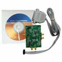
EVALUATION BOARD FOR LMX25120967
Manufacturer
National Semiconductor
Series
PLLatinum™r
Datasheets
1.LMX2512LQ0967NOPB.pdf
(18 pages)
2.LMX2430EVAL.pdf
(8 pages)
3.LMX25120967EVALNOPB.pdf
(24 pages)
Specifications of LMX25120967EVAL/NOPB
Main Purpose
Timing, Frequency Synthesizer
Embedded
No
Utilized Ic / Part
LMX2512
Primary Attributes
Single Fractional-N and Integer-N PLL with VCO
Secondary Attributes
967MHz, CodeLoader Graphical User Interface
Lead Free Status / RoHS Status
Lead free / RoHS Compliant
Other names
*LMX25120967EVAL
*LMX25120967EVAL/NOPB
LMX25120967EVAL
*LMX25120967EVAL/NOPB
LMX25120967EVAL


3
3.1
Measure the phase noise characteristics of the PLL with spectrum analyzer or a VCO/PLL
analyzer. The phase noise plots in these instructions are from a VCO analyzer and give an
overall picture of the phase noise of the LMX2512LQ0967. The VCO analyzer provides plots of
the phase noise over a span of offset frequencies giving the designer a more complete indication
of a device’s overall phase noise performance.
For phase noise measurements at fixed offset frequencies, use an analyzer with a noise floor
below the level of measurement interest. Since they are more readily available, below is an
explanation of this test technique using a spectrum analyzer.
Tune the spectrum analyzer to the desired center frequency with the span adjusted to include the
appropriate offset frequency. Using the delta marker, the difference between the carrier and the
noise level at the desired offset frequency is measured. The video averaging feature of the
spectrum analyzer should used to better determine the noise level.
The phase noise is a 1 Hz normalized bandwidth measurement expressed in dBc/Hz. Most
modern spectrum analyzers have a feature that automatically normalizes the phase noise
measurements to a 1 Hz bandwidth. This feature gives greater measurement accuracy. For
spectrum analyzers without this feature, the normalized phase noise is equal to the noise level
relative to the carrier minus 10 * log
For accurate close-in phase noise measurements, the offset frequency selected should be inside
the loop bandwidth on the flat portion of the curve.
With either measurement method, VCO analyzer or spectrum analyzer, care should be taken to
ensure the noise floor of the instrument does not limit the phase noise measurement.
LMX2512LQ0967
4. Verify that jumper blocks JP1 and JP2 contain a full compliment of shunts. JP1 connects
5. Turn the DC power supply ON and adjust the voltage output to 5.0 V. Turn the DC power
6. Connect the DC power supply output to the VDD_5V port of the evaluation board. Turn
7. Run the CodeLoader software for LMX2512 register programming. Ensure proper port
Measurement Considerations
Phase Noise Measurement
the 5.0 V supply input (VDD_5V) to the on board regulator.
additional regulator circuit and TCXO are included on the layout but not placed. JP2
connects the 2.8 V regulated supply to various supply pins on the LMX2512 and the IF
VCO.
supply OFF.
the DC power supply ON.
setup and that the reference frequency matches the CodeLoader programming in the
Bits/Pins and RF and IF PLL tabs. Refer to Appendix E for more details.
LMX2512LQ0967 EVALUATION BOARD OPERATING INSTRUCTIONS
10
[Resolution Bandwidth].
February 21, 2003
For convenience, an
2
Related parts for LMX25120967EVAL/NOPB
Image
Part Number
Description
Manufacturer
Datasheet
Request
R

Part Number:
Description:
National Semiconductor [8-Bit D/A Converter]
Manufacturer:
National Semiconductor
Datasheet:
Part Number:
Description:
National Semiconductor [Media Coprocessor]
Manufacturer:
National Semiconductor
Datasheet:
Part Number:
Description:
Digitally Controlled Tone and Volume Circuit with Stereo Audio Power Amplifier, Microphone Preamp Stage and National 3D Sound
Manufacturer:
National Semiconductor
Datasheet:
Part Number:
Description:
Digitally Controlled Tone and Volume Circuit with Stereo Audio Power Amplifier, Microphone Preamp Stage and National 3D Sound
Manufacturer:
National Semiconductor
Datasheet:
Part Number:
Description:
AC97 Rev 2 Codec with Sample Rate Conversion and National 3D Sound
Manufacturer:
National Semiconductor
Part Number:
Description:
Manufacturer:
National Semiconductor
Datasheet:
Part Number:
Description:
Manufacturer:
National Semiconductor
Datasheet:
Part Number:
Description:
General Purpose, Low Voltage, Low Power, Rail-to-Rail Output Operational Amplifiers
Manufacturer:
National Semiconductor
Datasheet:
Part Number:
Description:
8-bit 20 MSPS flash A/D converter.
Manufacturer:
National Semiconductor
Datasheet:
Part Number:
Description:
Low Noise Quad Operational Amplifier
Manufacturer:
National Semiconductor
Datasheet:
Part Number:
Description:
Quad Differential Line Receivers
Manufacturer:
National Semiconductor
Datasheet:
Part Number:
Description:
Quad High Speed Trapezoidal? Bus Transceiver
Manufacturer:
National Semiconductor
Datasheet:
Part Number:
Description:
Dual Line Receiver
Manufacturer:
National Semiconductor
Datasheet:
Part Number:
Description:
TTL to 10k ECL Level Translator with Latch
Manufacturer:
National Semiconductor
Datasheet: