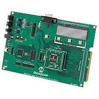
MCP3901EV-MCU16 Microchip Technology, MCP3901EV-MCU16 Datasheet - Page 13

MCP3901EV-MCU16
Manufacturer Part Number
MCP3901EV-MCU16
Description
BOARD EVAL FOR 2CH ADC MCP3901
Manufacturer
Microchip Technology
Datasheets
1.MCP3901A0-ISS.pdf
(60 pages)
2.MCP3901A0-ISS.pdf
(30 pages)
3.MCP3901EV-MCU16.pdf
(38 pages)
4.MCP3901EV-MCU16.pdf
(38 pages)
Specifications of MCP3901EV-MCU16
Number Of Adc's
2
Number Of Bits
24
Data Interface
SPI™
Inputs Per Adc
1 Differential
Input Range
±1 V
Voltage Supply Source
Analog and Digital
Operating Temperature
-40°C ~ 85°C
Utilized Ic / Part
MCP3901
Silicon Manufacturer
Microchip
Application Sub Type
ADC
Kit Application Type
Data Converter
Silicon Core Number
MCP3901, PIC24F, PIC24H, DsPIC33, PIC18F86J55
Kit Contents
Board
Lead Free Status / RoHS Status
Lead free / RoHS Compliant
2010 Microchip Technology Inc.
2.1.3
One of the major tasks in energy meter design is to minimize the effect of the power
factor variations on measurement accuracy. In order to have accurate measurements
over a wide range of power factors, it is necessary to have the same delays on both
current and voltage channels. Any difference in values between the two delays will
cause undesirable variations in the measurement of power and energy, as shown on
the display, according to the power factor. The external passive components can
induce a phase shift because of the part’s value tolerances.
The MCP3901 device contains a phase delay compensation block that adds extra
delays on one channel relative to the other, compensating for the power factor
variations.
The extra delays added are controlled by the user through an internal Phase Delay reg-
ister (kk) on the MCP3901 device. Figure 2-3 illustrates the measurement accuracy at
different power factors and for different Phase Delay register values. It shows how a
small delay was necessary on one of the channels to achieve minimum errors on a
wider range of angles.
FIGURE 2-3:
The value of the Phase Delay register is automatically computed during the meter cal-
ibration routine. Power meter calibration and all of the processes that are performed
are described in Section 2.2 “Calibration Procedure”.
Once written into the MCP3901 ADC Phase Delay register, the Phase Delay block
inside the MCP3901 ADC compensates for power-factor-related errors. This method
decreases the computation requirement on the PIC18F25K20 MCU.
-90
Power Factor Compensation
Angle (degrees)
-60
Error VS Angle VS Phase Delay Register (kk)
Error vs. Phase Angle vs. Phase Delay Register.
-30
-0.05
-0.15
-0.25
0.25
0.15
0.05
-0.1
-0.2
-0.3
0.2
0.1
0
0
30
60
DS51915A-page 13
kk=-1
kk=-2
kk=0
kk=1
90


