MCP3901EV-MCU16 Microchip Technology, MCP3901EV-MCU16 Datasheet - Page 19
MCP3901EV-MCU16
Manufacturer Part Number
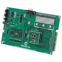
MCP3901EV-MCU16
Description
BOARD EVAL FOR 2CH ADC MCP3901
Manufacturer
Microchip Technology
Datasheets
1.MCP3901A0-ISS.pdf
(60 pages)
2.MCP3901A0-ISS.pdf
(30 pages)
3.MCP3901EV-MCU16.pdf
(38 pages)
4.MCP3901EV-MCU16.pdf
(38 pages)
Specifications of MCP3901EV-MCU16
Number Of Adc's
2
Number Of Bits
24
Data Interface
SPI™
Inputs Per Adc
1 Differential
Input Range
±1 V
Voltage Supply Source
Analog and Digital
Operating Temperature
-40°C ~ 85°C
Utilized Ic / Part
MCP3901
Silicon Manufacturer
Microchip
Application Sub Type
ADC
Kit Application Type
Data Converter
Silicon Core Number
MCP3901, PIC24F, PIC24H, DsPIC33, PIC18F86J55
Kit Contents
Board
Lead Free Status / RoHS Status
Lead free / RoHS Compliant


2010 Microchip Technology Inc.
The appropriate Phase Delay register value is determined by the measurement of the
indication variation during the following calibration routine.
As calibration is initiated, the values of the Active Power Scaling Factor, RMS Current
Scaling Factor, and RMS Voltage Scaling Factor at a Power Factor of 1 are determined
through the following process:
1. Supplying the meter with the following values: 110 of V
2. Powering the monitor with 110V of U
3. Powering the meter with 110V of U
The two power values measured at -45 and +45 degrees are inserted into the equation
in Figure 2-8, and the result is the Phase Delay register value required to compensate
for the power factor variation.
at 0 degrees
The meter takes a few seconds (maximum 20 s) to get stable readings, then the
PC virtual port sends the character “c” from the PC to the power monitor. The
pulse output LED stops blinking for a few seconds, and the LCD shows “Calibrat-
ing 110V 5A PF=1”. The three constants will be computed and saved to the
EEPROM of the MCU. Power can be interrupted without losing this calibration
information.
The meter takes a few seconds to get stable readings, then the PC virtual port
sends the character “n” (negative phase) from the PC to the power monitor. The
the pulse output LED is forced ON for a few seconds, while the LCD shows “Cal-
ibrating for -45 degrees”. The results collected during this step are not saved into
the EEPROM of the MCU. It is important that power is not lost until after Step 3
is complete.
The meter takes a few seconds to get stable readings, then the PC virtual port
sends the character “p” (positive phase) from the PC to the power monitor. The
pulse output LED is forced ON for a few seconds, while the LCD shows “Calibrat-
ing for +45 degrees”. When this step finishes, the calibration parameters are
saved into the EEPROM. Now power can be disconnected from the meter.
RMS
RMS
, 5A of I
, 5V of I
RMS
RMS
and Phase at 45 degrees.
and a Phase at -45 degrees
RMS
, 5 A
RMS
DS51915A-page 19
, and Phase
Related parts for MCP3901EV-MCU16
Image
Part Number
Description
Manufacturer
Datasheet
Request
R

Part Number:
Description:
Manufacturer:
Microchip Technology Inc.
Datasheet:
Part Number:
Description:
Manufacturer:
Microchip Technology Inc.
Datasheet:
Part Number:
Description:
Manufacturer:
Microchip Technology Inc.
Datasheet:
Part Number:
Description:
Manufacturer:
Microchip Technology Inc.
Datasheet:
Part Number:
Description:
Manufacturer:
Microchip Technology Inc.
Datasheet:
Part Number:
Description:
Manufacturer:
Microchip Technology Inc.
Datasheet:
Part Number:
Description:
Manufacturer:
Microchip Technology Inc.
Datasheet:
Part Number:
Description:
Manufacturer:
Microchip Technology Inc.
Datasheet: