AD9262-10EBZ Analog Devices Inc, AD9262-10EBZ Datasheet
AD9262-10EBZ
Specifications of AD9262-10EBZ


Related parts for AD9262-10EBZ


AD9262-10EBZ Summary of contents
Page 1
... The ADL5382 covers the frequency range between 700 MHz and 2.7 GHz. The AD9262 has passive inputs, therefore allowing the ADL5382 to directly drive the ADC. The AD9262 does not require a filter preceding the converter because the continuous time sigma- delta architecture possesses inherent antialiasing capabilities. ...
Page 2
... Differential Transformer Path .................................................... 6 ADC Driver Path .......................................................................... 6 Supporting Hardware and Software ............................................... 7 REVISION HISTORY 1/10—Revision 0: Initial Version Evaluation Board User Guide Software ..........................................................................................7 Hardware ........................................................................................7 AD9262 SPI Controller ................................................................7 AD9516 SPI Controller ................................................................7 AD9516 Register Settings .............................................................8 VisualAnalog Overview ................................................................9 Schematics ....................................................................................... 10 Layout ............................................................................................... 15 ...
Page 3
... Evaluation Board User Guide PRODUCT FEATURES Table 1. AD9262 ADL5382 SNR: 82.5 dB (84.5 dBFS) to I/Q demodulator 10 MHz input Operating RF frequency: 700 MHz to SFDR: 87 dBc to 10 MHz input Noise figure IIP3 + 30 dBm Input impedance: 1 kΩ IIP2 + 60 dBm Power: 675 mW Input P1dB + 13dBm 1 ...
Page 4
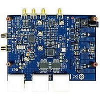
... GETTING STARTED Figure 2. Evaluation Board Front The default configuration of the AD9262 evaluation board allows a quick and easy start to evaluating the direct conversion receiver subsystem. The default configuration interfaces the ADL5382 directly with the AD9262. Table 2 and Figure 4 show the hardware required to start the evaluation ...
Page 5
... Channel A and Channel B, respectively, of the AD9262. BYPASS_LDO Additionally, short TP17, TP23, TP2, and TP24 to the appropriate pads to route the external signals to the input pins of the AD9262 (see Figure 7). This configuration requires careful attention to ensure that the output signals of the ADL5382 are disconnected and only the signals from the transformer or ADA4937 are routed to the ADC ...
Page 6
... Table 5. External ADC Input Configuration Connector Setting Notes J4, J5 J4: Channel B J5: Channel A R33 to 42 DNP Disconnect ADL5382 outputs from the AD9262 TP17 Connect A+ path Short to the closest pad on R40 TP23 Short to the closest Connect A− path pad on R39 TP2 Short to the closest ...
Page 7
... The switching power supplies have different output voltages. Connect the 6 V power supply to the AD9262 evaluation board and the 5 V power supply to the HSC-ADC- EVALCZ data capture board. With the HSC-ADC-EVALCZ ...
Page 8
UG-051 Figure 10. AD9516 REGISTER SETTINGS The SPIController uses a 4-wire interface; therefore, the AD9516 must be configured for this interface before any further writes can take effect. To configure the AD9516, check the SDO Enable bit, as shown in ...
Page 9
... A/B Counter 0/5 4/5 Prescaler 16/17 16/17 Output CLK 672 MHz 645.12 MHz VisualAnalog OVERVIEW Open VisualAnalog and choose a canvas from the AD9262 folder (see Figure 14). 39.3216 MHz 2.595 GHz 1 2/4 16/17 648.81 MHz Rev Page UG-051 Figure 14. VisualAnalog Canvas ...
Page 10
... UG-051 SCHEMATICS FL1 BNX016- 1. C54 3 10UF A 3 CR8 PJ-102A 10BQ015TRPBF GND TP11 1 BLK AGND POWER SUPPLY AD9262 AVDD: +1.8V CVDD: +1.8V DVDD: +1.8V DRVDD: +1.8V AD9516-0: +3.3V ADL5382: +5V ADA4937-2: +5V BERG69157-102 +6V P12 TP10 1 RED A2 ADP3339AKCZ-5- GND 1 4 C62 4 1UF 6 5 AGND AGND ...
Page 11
... CSB 49 RESET 50 AGND 51 AVDD 52 VIN+A 53 VIN-A 54 AVDD 55 VREF 56 CFILT 57 AVDD 58 VIN+B 59 VIN-B 60 AVDD 61 AGND 62 CGND 63 CLK Figure 16. AD9262 Pinout Rev Page UG-051 08471-009 10K R51 10K R50 68 D5A 32 D4A 31 D3A 30 D2A 29 D1A 28 D0A 27 DCO 26 DVDD 25 DGND 24 DRVDD 23 ORB 22 D15B 21 D14B 20 D13B ...
Page 12
UG-051 Figure 17. Data Interface to the HSC-ADC-EVALCZ High Speed ADC Data Capture Card (RED) LNJ208R8ARA 301 A C R20 CR6 TBD0402 C200 HEADER ...
Page 13
... Evaluation Board User Guide COM COM -OUT1 19 PD1 20 -VS1 21 -VS1 22 FB-OUT1 23 +IN1 COM COM +OUT2 12 VOCM2 11 +VS2 10 +VS2 9 FB+OUT2 8 -IN2 7 PAD Figure 18. AD9262 Input Configuration Rev Page UG-051 08471-011 PAD VPA CMRF VPL CML VPB VPX COM L1 L2 120NH 120NH 142-0711-201 142-0711-201 ...
Page 14
UG-051 Figure 19. AD9516-0 Configuration Rev Page 14 of ...
Page 15
Evaluation Board User Guide LAYOUT Figure 20. Top Silk Rev Page UG-051 ...
Page 16
UG-051 Evaluation Board User Guide Figure 21. Bottom Silk Rev Page ...
Page 17
Evaluation Board User Guide +5V AVDD CVDD Figure 22. Power 1: Layer 3 Rev Page UG-051 ...
Page 18
UG-051 Evaluation Board User Guide DVDD DRVDD AD9516_+3p3V Figure 23. Power 2: Layer 4 Rev Page ...
Page 19
Evaluation Board User Guide ORDERING INFORMATION BILL OF MATERIALS Table 9. Qty Reference Designators C1, C2, C5, C7, C8, C15, C16, C20, C21, C26, C27, C28, C29, C30, C32, C35, C36, C41, C85, ...
Page 20
UG-051 Qty Reference Designators 4 C71, C72, C73, C74 1 C80 1 CR1 3 CR9, CR13, CR14 4 CR2, CR3, CR4, CR5 2 CR6, CR7 1 CR8 6 E3, E4, E5, E6, E7 FL1 5 J1, ...
Page 21
Evaluation Board User Guide Qty Reference Designators 4 R10, R12, R27, R49 1 R11 1 R13 4 R14, R15, R16, R17 12 R18, R43, R44, R45, R46, R48, R68, R70, R88, R89, R90, R91 9 R9, R19, R22, R24, R47, ...
Page 22
... Digi-Key TP-104-01-02 5005K-ND 5006 Digi-Key TP-104-01-00 5006K-ND 5007 Digi-Key TP-104-01-09 5007K-ND 5015 Digi-Key TP-108-01 5015KCT-ND 5009 Digi-Key TP-104-01-04 5009K-ND AD9262 74VCX16827MTD Mouser 512-74VCX16827 MTD ADA4937-2 NC7WZ07P6X Mouser 512-NC7WZ 07P6X Digi-Key NC7WZ07P6XCT-ND SN74LVC2G14 Mouser 595-SN74LVC DBVR 2G14 DBVR Digi-Key 296-13010-1-ND ADR130BUJZ AD9516-0BCPZ ...
Page 23
Evaluation Board User Guide NOTES Rev Page UG-051 ...
Page 24
UG-051 NOTES ESD CAUTION Evaluation boards are only intended for device evaluation and not for production purposes. Evaluation boards are supplied “as is” and without warranties of any kind, express, implied, or statutory including, but not limited to, any implied ...