ADC101C02XEB/NOPB National Semiconductor, ADC101C02XEB/NOPB Datasheet - Page 22
ADC101C02XEB/NOPB
Manufacturer Part Number
ADC101C02XEB/NOPB
Description
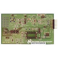
BOARD EVALUATION FOR ADC101C02X
Manufacturer
National Semiconductor
Specifications of ADC101C02XEB/NOPB
Number Of Adc's
1
Number Of Bits
10
Sampling Rate (per Second)
188.9k
Data Interface
I²C
Inputs Per Adc
1 Single Ended
Power (typ) @ Conditions
780mW @ 22kSPS
Voltage Supply Source
Single Supply
Operating Temperature
-40°C ~ 105°C
Utilized Ic / Part
ADC101C021, ADC101C027
Silicon Manufacturer
National
Silicon Core Number
ADC101C021, ADC101C027
Kit Application Type
Data Converter
Application Sub Type
ADC
Kit Contents
Board
Lead Free Status / RoHS Status
Lead free / RoHS Compliant
Other names
ADC101C02XEB


www.national.com
1.7.4 I
The ADC has a seven-bit hardware address which is also re-
ferred to as a slave address. For the MSOP-8 version of the
ADC101C021, this address is configured by the ADR0 and
ADR1 addres selection inputs. For the ADC101C027, the ad-
dress is configured by the ADR0 address selection input.
ADR0 and ADR1 can be grounded, left floating, or tied to
V
The state of these inputs sets the hardware address that the
1.8 ALERT FUNCTION
The ALERT function is an "out-of-range" indicator. At the end
of every conversion, the measured voltage is compared to the
values in the V
age exceeds the value stored in V
stored in V
is indicated in up to three places. First, the alert condition al-
ways causes either or both of the alert flags in the Alert Status
register to go high. If the measured voltage exceeds the
V
voltage falls below the V
is set. Second, if the Alert Flag Enable bit is set in the Con-
figuration register, the alert condition also sets the MSB of the
Conversion Result register. Third, if the Alert Pin Enable bit is
set in the Configuration register, the ALERT output becomes
active (see Figure 9). The ALERT output (ADC101S021 only)
can be configured as an active high or active low output via
the Polarity bit in the Configuration register. If the Polarity bit
is cleared, the ALERT output is configured as active low. If
A
HIGH
. If desired, ADR0 can be set to V
limit, the Over Range Alert Flag is set. If the measured
2
C Slave (Hardware) Address
LOW
Slave Address
, an alert condition occurs. The Alert condition
HIGH
[A6 - A0]
1010000
1010001
1010010
1010100
1010101
1010110
1011000
1011001
1011010
and V
LOW
LOW
limit, the Under Range Alert Flag
registers. If the measured volt-
HIGH
A
/2 rather than left floating.
ADC101C027
or falls below the value
-----------------
-----------------
-----------------
-----------------
-----------------
-----------------
FIGURE 8. Beginning Hs-Mode Communication
(TSOT-6)
Floating
ADR0
GND
V
A
TABLE 1. Slave Addresses
Single Address
ADC101C021
-----------------
-----------------
-----------------
-----------------
-----------------
-----------------
-----------------
-----------------
(TSOT-6)
ALERT
22
ADC responds to on the I
TSOT-6 version of the ADC101C021, the hardware address
is not pin-configurable and is set to 1010100. The diagrams
in Section 1.10 COMMUNICATING WITH THE AD-
C101C021 describe how the I
ADC via the I
Pin compatible alternatives that provide additional address
options to the TSOT-6 version of the ADC101C021 and the
ADC101C027 are available.
the Polarity bit is set, the ALERT output is configured as active
high.
The Over Range Alert condition is cleared when one of the
following two conditions is met:
1.
2.
The Under Range Alert condition is cleared when one of the
following two conditions is met:
1.
2.
The controller writes a one to the Over Range Alert Flag
bit.
The measured voltage goes below the programmed
V
Alert Hold bit is cleared in the Configuration register. (see
Figure 9). If the Alert Hold bit is set, the alert condition
persists and only clears when a one is written to the Over
Range Alert Flag bit.
The controller writes a one to the Under Range Alert Flag
bit.
The measured voltage goes above the programmed
V
HIGH
LOW
limit plus the programmed V
limit minus the programmed V
2
C interface.
Floating
Floating
Floating
ADR1
GND
GND
GND
V
V
V
A
A
A
ADC101C021
(MSOP-8)
2
C bus (see Table 1). For the
2
C controller should address the
Floating
Floating
Floating
ADR0
GND
GND
GND
V
V
V
HYST
A
A
A
HYST
value and the
value and the
30052012
Related parts for ADC101C02XEB/NOPB
Image
Part Number
Description
Manufacturer
Datasheet
Request
R

Part Number:
Description:
National Semiconductor [8-Bit D/A Converter]
Manufacturer:
National Semiconductor
Datasheet:
Part Number:
Description:
National Semiconductor [Media Coprocessor]
Manufacturer:
National Semiconductor
Datasheet:
Part Number:
Description:
Digitally Controlled Tone and Volume Circuit with Stereo Audio Power Amplifier, Microphone Preamp Stage and National 3D Sound
Manufacturer:
National Semiconductor
Datasheet:
Part Number:
Description:
Digitally Controlled Tone and Volume Circuit with Stereo Audio Power Amplifier, Microphone Preamp Stage and National 3D Sound
Manufacturer:
National Semiconductor
Datasheet:
Part Number:
Description:
AC97 Rev 2 Codec with Sample Rate Conversion and National 3D Sound
Manufacturer:
National Semiconductor
Part Number:
Description:
Manufacturer:
National Semiconductor
Datasheet:
Part Number:
Description:
Manufacturer:
National Semiconductor
Datasheet:
Part Number:
Description:
General Purpose, Low Voltage, Low Power, Rail-to-Rail Output Operational Amplifiers
Manufacturer:
National Semiconductor
Datasheet:
Part Number:
Description:
8-bit 20 MSPS flash A/D converter.
Manufacturer:
National Semiconductor
Datasheet:
Part Number:
Description:
Low Noise Quad Operational Amplifier
Manufacturer:
National Semiconductor
Datasheet:
Part Number:
Description:
Quad Differential Line Receivers
Manufacturer:
National Semiconductor
Datasheet:
Part Number:
Description:
Quad High Speed Trapezoidal? Bus Transceiver
Manufacturer:
National Semiconductor
Datasheet:
Part Number:
Description:
Dual Line Receiver
Manufacturer:
National Semiconductor
Datasheet:
Part Number:
Description:
TTL to 10k ECL Level Translator with Latch
Manufacturer:
National Semiconductor
Datasheet: