SSM2305-EVALZ Analog Devices Inc, SSM2305-EVALZ Datasheet - Page 5
SSM2305-EVALZ
Manufacturer Part Number
SSM2305-EVALZ
Description
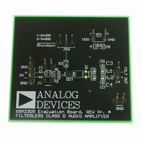
BOARD EVAL FOR SSM2305 LFCSP
Manufacturer
Analog Devices Inc
Specifications of SSM2305-EVALZ
Amplifier Type
Class D
Output Type
1-Channel (Mono)
Max Output Power X Channels @ Load
2.8W x 1 @ 4 Ohm
Voltage - Supply
2.2 V ~ 5.5 V
Operating Temperature
-40°C ~ 85°C
Board Type
Fully Populated
Utilized Ic / Part
SSM2305
Silicon Manufacturer
Analog Devices
Application Sub Type
Audio Power Amplifier - Class D
Kit Application Type
Amplifier
Silicon Core Number
SSM2305
Kit Contents
Board
Lead Free Status / RoHS Status
Lead free / RoHS Compliant


6.
7.
8.
A 1 nF capacitor and the ferrite bead can block the EMI for
up to 250 MHz. To eliminate EMI higher than 250 MHz,
place a low value, small size capacitor, such as a 100 pF,
0402 size capacitor, in parallel with the 1 nF decoupling
capacitor.
Place this small capacitor a small distance away from the
1 nF capacitor and use the PCB connection track as an
inductor to form a PI shape, low-pass filter, as shown in
Figure 5.
If implementing a PCB track PI filter, do not connect the
arriving input PCB track and the leaving output PCB track
to the decoupling capacitor.
The correct layout is shown in Figure 5. The incorrect
layout is shown in Figure 6.
Decouple the input port nodes with small capacitors, such
as 100 pF capacitors. They are not necessary but can lower
the input EMI.
Figure 6. Incorrect Routing for the Inductive Track Output
C12
C8
Decoupling Capacitor
C9
C10
C13
C11
INPUT
TRACK
OUTPUT
TRACK
Rev. 0 | Page 5 of 8
GETTING STARTED
To ensure proper operation, carefully follow Step 1 through Step 4.
1.
2.
3.
4.
WHAT TO TEST
When implementing the SSM2305 evaluation board, test the
board for the following:
•
•
•
•
•
•
Ensure proper connection of the input terminals. For
single-ended input, be sure to ground the unused audio
input terminal; otherwise, you will encounter poor audio
quality.
To activate the SSM2305, place a jumper across Pin 1 and
Pin 2 (the left and center terminals) of JP6 and make sure
that the SD pin is pulled up to VDD.
Connect the load across the output ports.
Connect the power supply with the correct polarity and
proper voltage.
Electromagnetic interference (EMI)—connect wires for the
speakers, making sure they are the same length as the wires
required for the actual application environment; then
complete the EMI test.
Signal-to-noise ratio (SNR).
Output noise—make sure to use an A-weighted filter to
filter the output before reading the measurement meter.
Maximum output power.
Distortion.
Efficiency.
EVAL-SSM2305
Related parts for SSM2305-EVALZ
Image
Part Number
Description
Manufacturer
Datasheet
Request
R

Part Number:
Description:
±1.7g Dual-Axis IMEMS Accelerometer Evaluation Board
Manufacturer:
Analog Devices Inc
Datasheet:

Part Number:
Description:
Inertial Sensor Evaluation System
Manufacturer:
Analog Devices Inc
Datasheet:
Part Number:
Description:
Manufacturer:
Analog Devices Inc
Datasheet:
Part Number:
Description:
Manufacturer:
Analog Devices Inc
Datasheet:
Part Number:
Description:
Manufacturer:
Analog Devices Inc
Datasheet:
Part Number:
Description:
Manufacturer:
Analog Devices Inc
Datasheet:
Part Number:
Description:
Manufacturer:
Analog Devices Inc
Datasheet:
Part Number:
Description:
Manufacturer:
Analog Devices Inc
Datasheet:
Part Number:
Description:
Manufacturer:
Analog Devices Inc
Datasheet:
Part Number:
Description:
Manufacturer:
Analog Devices Inc
Datasheet:
Part Number:
Description:
Manufacturer:
Analog Devices Inc
Datasheet:
Part Number:
Description:
Manufacturer:
Analog Devices Inc
Datasheet:
Part Number:
Description:
Manufacturer:
Analog Devices Inc
Datasheet: